Technique for cancellation of elevated clutter for the detection of fixed and ground moving targets under trees

a technology of elevated clutter and detection of fixed and ground moving targets, applied in the field of above ground clutter cancellation for use with synthetic aperture radar imaging, can solve the problems of inability to reliably detect targets in satellite imaging, and failure of vhf and uhf approaches in many instances, and achieve the effect of facilitating tracking of moving targets

Active Publication Date: 2006-05-25
RAYTHEON CO
View PDF16 Cites 19 Cited by
  • Summary
  • Abstract
  • Description
  • Claims
  • Application Information

AI Technical Summary

Benefits of technology

[0015] A plurality of uncluttered images are examined to extract motion parameters and features of moving targets on the surface. The plurality of uncluttered images are thresholded with respect to a noise estimate of one or more of the uncluttered images to facilitate tracking of moving target on the surface.

Problems solved by technology

However, where ground targets of interest are under a forest canopy or some other vegetative cover, the SAR imaging may not reliably detect the targets.
However, this VHF and UHF approach failed in many instances.

Method used


Image

  • Technique for cancellation of elevated clutter for the detection of fixed and ground moving targets under trees
  • Technique for cancellation of elevated clutter for the detection of fixed and ground moving targets under trees
  • Technique for cancellation of elevated clutter for the detection of fixed and ground moving targets under trees

Examples


embodiment

PREFERRED EMBODIMENT

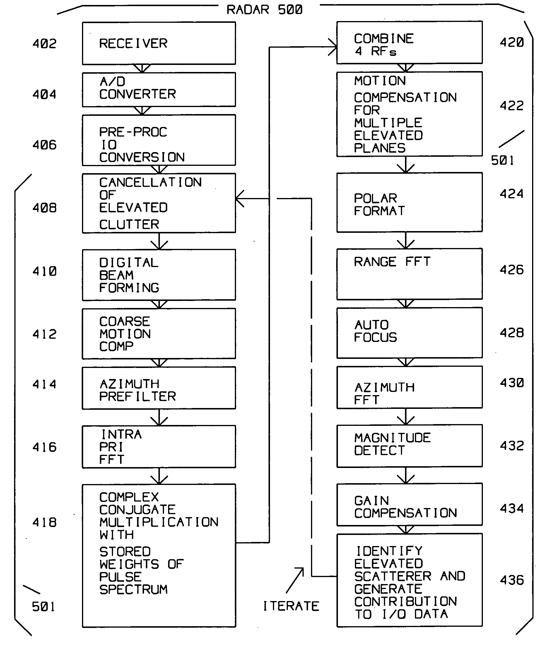
[0035]FIG. 4 shows method steps of a preferred embodiment of the invention. Receiver 402 receives radar returns reflected from the combination of target 313 as well as elevated clutter 301, 303 and 305. 8 channels are used for a 6 KM swath. A / D converter 404 digitizes the received radar returns at a rate corresponding to the desired range bin size. An 80 MHz rate (real), 12 bits / channel is utilized to produce a 2 K range pixel by 2 K cross range pixel map with 4 meter resolution and 1 meter azimuth resolution in 60 seconds.

[0036] The digital values from A / D converter 404 become the I and Q complex values defining the phase of the return. Preprocessor I / Q conversion 406 uses a weight of 16, skip 4, real processing using a 14 MHz pass band, 20 MHz output sample rate, generating 2 bytes for 1 and 2 bytes for Q. The output is 20 Mega-complex words at 4 bytes per word per second, assuming a 50 percent margin. SAR PRF is selected to eliminate sidelobe foldovers.

[0037...


PUM


Abstract

A target is detected under a forest canopy or other elevated clutter where the target is obscured by the elevated clutter. Radar returns reflected from the target on the surface, combined with those from the elevated clutter are digitized. Motion compensation is performed for the radar returns with respect to the target to obtain a focused first synthetic aperture image of the target. Next, the radar returns are motion compensated with respect to the elevated clutter at various heights above the surface to obtain images of the elevated clutter. The elevated clutter within the images at the various heights above the surface is identified and coherently subtracted from the original synthetic aperture images.

Description

BACKGROUND OF THE INVENTION [0001] 1. Field of the Invention [0002] This invention is in the field of above ground clutter canceling for use with Synthetic Aperture Radar imaging. [0003] 2. Description of the Related Art [0004] Synthetic Aperture Radar (SAR) radar is used for ground mapping as well as target identification. The general principle behind SAR is to coherently combine the amplitude and phase information of radar returns from a plurality of sequentially transmitted pulses from a relatively small antenna on a moving platform. [0005] The plurality of returns creating a SAR image generated by the transmitted pulses along a known path of the platform make up a frame length. During the frame length, amplitude as well as phase information returned from each of the pulses, for each of many range bins, is preserved. The SAR image is formed from the coherent combination of the amplitude and phase of return(s) within each range bin, motion compensated for spatial displacement of t...

Claims


Application Information

Patent Timeline
Patent Type & Authority Applications(United States)
IPC IPC(8): G01S13/90
CPCG01S13/90G01S13/9019
Inventor KRIKORIAN, KAPRIEL V.ROSEN, ROBERT A.
Owner RAYTHEON CO
Why Eureka
Try Eureka