Diffuser, wavefront source, wavefront sensor and projection exposure apparatus

a technology of wavefront sensor and diffuser, which is applied in the direction of optical radiation measurement, photomechanical equipment, instruments, etc., to achieve the effect of sufficient scattering capability

Inactive Publication Date: 2006-05-25
CARL ZEISS SMT GMBH +1
View PDF5 Cites 22 Cited by
  • Summary
  • Abstract
  • Description
  • Claims
  • Application Information

AI Technical Summary

Benefits of technology

[0016] It is found that such a diffractive CGH scattering structure, precisely also for the UV and especially EUV wavelength range, firstly can be dimensioned well and secondly can be realized with materials suitable for this wavelength range, and has a sufficient scattering capability.

Problems solved by technology

One difficulty in this context is that customary illumination systems such as are used in microlithography projection exposure apparatuses in order to supply the desired UV or EUV exposure radiation have a certain pupil parceling and, moreover, do not fill the entire numerical aperture of the projection objective.

Method used


Image

  • Diffuser, wavefront source, wavefront sensor and projection exposure apparatus
  • Diffuser, wavefront source, wavefront sensor and projection exposure apparatus
  • Diffuser, wavefront source, wavefront sensor and projection exposure apparatus

Examples


Embodiment Construction

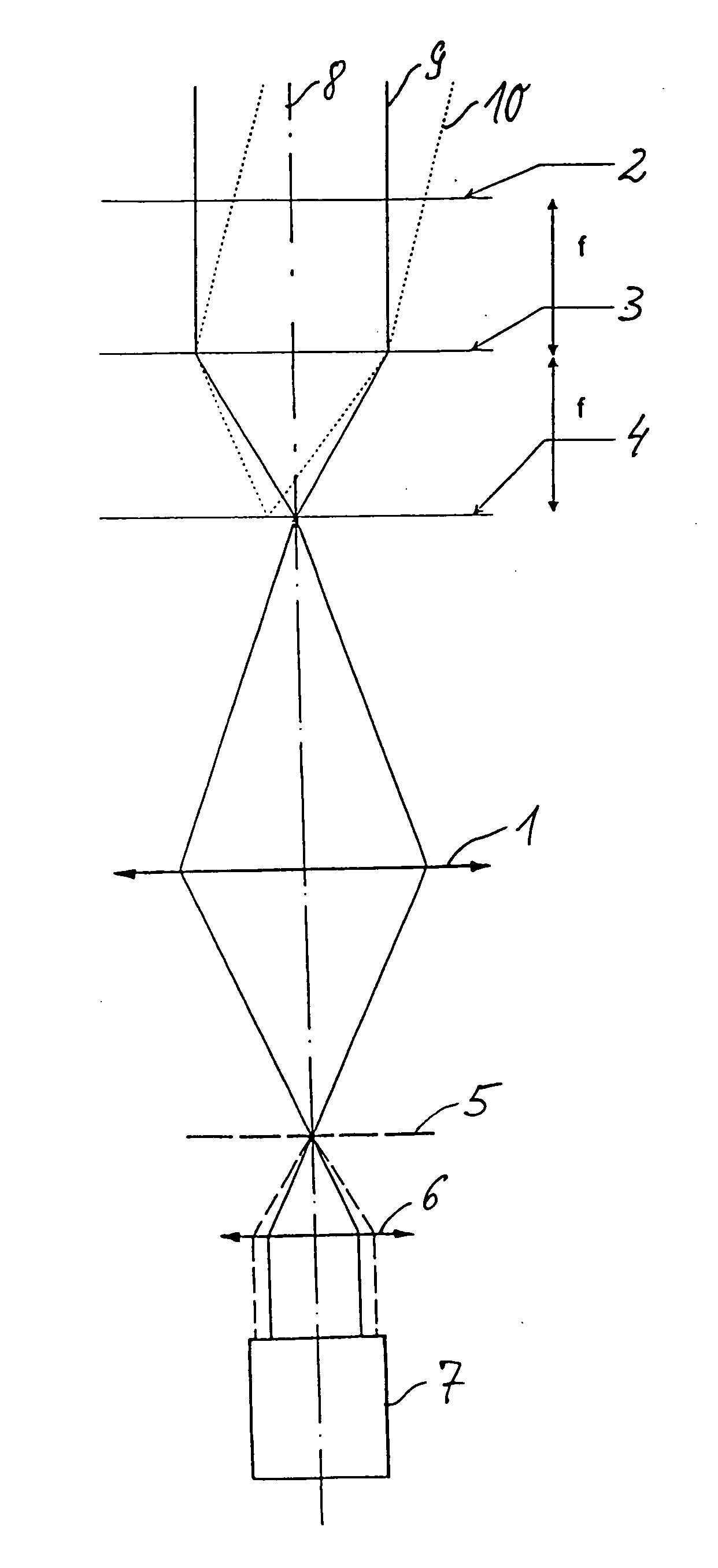
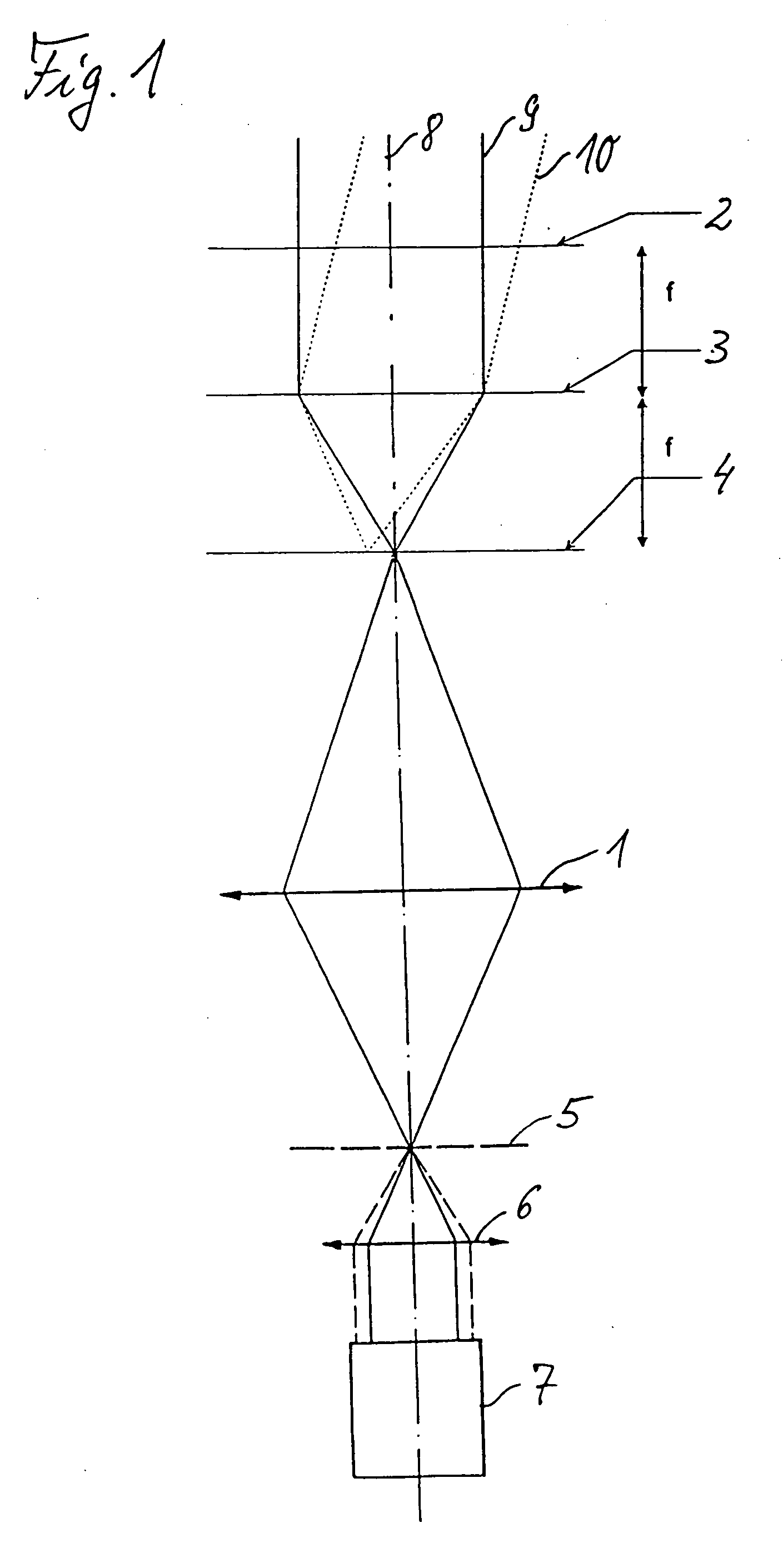
[0033]FIG. 1 schematically shows a device for interferometric wavefront measurement of an optical system 1, which, in particular, is a projection objective of a microlithography projection exposure apparatus. In this case, the device may be integrated into the projection exposure apparatus as a so-called operating interferometer in order to check the imaging quality of the projection objective 1 at its place of use from time to time, the measurement device preferably using the same radiation that is used by the apparatus in normal exposure operation and is supplied by an upstream illumination system (not shown in FIG. 1) customary for this purpose. Preferably UV radiation and especially EUV radiation may be involved in this case.

[0034] A wavefront source is arranged between the illumination system (not shown) and the projection objective 1 to be measured, said wavefront source serving for shaping radiation that comes from the illumination system into a wavefront radiation that is s...


PUM

PropertyMeasurementUnit
wavelengthsaaaaaaaaaa
sizesaaaaaaaaaa
sizesaaaaaaaaaa

Abstract

A wavefront source having a wavefront formation structure (4a) and a diffuser with a scattering structure (2b) in the beam path in front of or at the level of the wavefront formation structure; also a diffuser configured to be used therefor, and a wavefront sensor equipped therewith, as well as a corresponding projection exposure apparatus. The diffuser has a diffractive computer-generated hologram (CGH) scattering structure with a predetermined angular scattering profile. The wavefront source includes such a diffuser and/or a focusing element with a reflecting diffractive focusing structure (3a) in the beam path at the level of the scattering structure or between the scattering structure (2b) and the wavefront formation structure (4a). The disclosed structures are used, e.g., in the wavefront measurement of projection objectives in microlithography projection exposure apparatuses in the EUV wavelength range.

Description

[0001] This application is a continuation application of international patent application PCT / EP03 / 08738 filed on Aug. 7, 2003 and claiming priority from German patent application 103 17 278.5 filed on Apr. 11, 2003. The complete disclosures of these two patent applications are incorporated into this application by reference. BACKGROUND OF THE INVENTION [0002] 1. Field of the Invention [0003] The invention relates to a diffuser having a scattering structure for a wavefront source, to a corresponding wavefront source comprising, in addition to the diffuser, a wavefront formation structure in the beam path after or at the level of the scattering structure, to an associated wavefront sensor and an associated projection exposure apparatus. [0004] 2. Description of the Related Art [0005] A wavefront source of this type is disclosed in the published patent application DE 101 09 929 A1 as part of a device for the wavefront measurement of optical systems by means of shearing interferometry,...

Claims


Application Information

Patent Timeline
Patent Type & Authority Applications(United States)
IPC IPC(8): G02B5/32G01J9/02G02B5/02G03F7/20
CPCG01J9/02G02B5/0252G02B5/0278G02B5/0284G03F7/70075
Inventor SCHRIEVER, MARTINHAIDNER, HELMUT
Owner CARL ZEISS SMT GMBH
Why Eureka
Try Eureka