Reflection type projecting screen, front projector system, and multi-vision projector system

a projector system and projector technology, applied in the field of projectors, can solve the problems of high power, poor contrast of projection light image, and high cost of screen production, and achieve the effect of effective use of screens

Inactive Publication Date: 2006-05-25
OLYMPUS CORP
View PDF6 Cites 31 Cited by
  • Summary
  • Abstract
  • Description
  • Claims
  • Application Information

AI Technical Summary

Benefits of technology

[0112] According to the multi-vision projector system, it is easy to form a plurality of viewing regions in the horizontal direction, inasmuch as the reflection type screen diffuses the incident light within the angle range which is not greater than 45° in the horizontal direction. When the angle range is greater than 45°, the images, which are positioned at a peripheral portion and which have large angles of view, are overlapped on one another, although it is possible to separate the images traveling on the optical axes. As a result, crosstalk easily occurs and it is difficult to form a plurality of viewing regions.
[0113] According to the multi-vision projector system of the present invention, it is possible to form the viewing region in which a specific one of the images is capable of being viewed in each of the predetermined directions when the images, which are projected by the projectors in directions different from one another, are projected towards the centers of predetermined directions based on the incident directions. Inasmuch as the sounds corresponding to the images are outputted to the viewing regions by the speakers, it is possible for the viewer to view the image and the sound in the viewing region without being obstructed by the other images and the other sounds. As a result, it is possible to simultaneously view the image and listen to the sound in each of the independent viewing regions while effectively using the screen.

Problems solved by technology

In the case of projecting an image such as a dynamic image, a static image, or the like on a screen by a projector such as a cine-projector, a projector, or the like, in order to appreciate the image in a conventional reflection type projecting screen, there is a problem in which contrast becomes poor in the image produced by the projection light, inasmuch as outside light is reflected on the screen in a bright room.
However, the above-mentioned conventional reflection type screens have the following problems.
As a result, there is a problem in which it is necessary to have a light source having high power.
Therefore, there is a problem in which the screen becomes expensive to produce.
As result, it is difficult to easily apply the art described in Japanese Patent Application Unexamined Publication No. 2003-287818 to a large-scale projecting screen.
However, there is a problem in which the reflection type projecting screen becomes very expensive to produce, inasmuch as the diffuse type liquid crystal layer is located on the back surface of the corner cube reflector and it is necessary to electrically control the diffuse type liquid crystal layer.
Although it is possible to reflect the light having a comparative high directivity with respect to an incident direction by forming the concave surface on the corner cube mirror in the art described in Japanese Patent Application Unexamined Publication No. 1993-150368, the reflection type screen becomes very expensive to produce inasmuch as it is necessary to form a correct concave shape on the corner cube mirror at great expense in both time and effort.
In addition, there is a problem in which it is impossible to obtain high image quality inasmuch as the image becomes irregular, in the case where an error becomes large with respect to the formation of the concave surface.
However, the above-mentioned conventional projector systems have the following problems.
In the case where one projector projects the image on one screen, there is a problem in which equipment such as a screen and a projection room becomes large and the utilization efficiency becomes poor, because the entire screen is occupied even if there are not many viewers.
Although it is possible to improve the efficiency with respect to the equipment because a plurality of images are projected on one screen in the multi-vision system, there is a problem in which other images obstruct viewing, in the case of projecting unrelated images.
In addition, it is problematic to project images of a confidential or delicate nature such as explanatory materials used in a conference, because the viewers positioned before the screen can view all of the images.
As a result, it is difficult to freely change the directivity of reflection light and it is difficult to strictly control the reflected direction and diffuse range in accordance with the incident angle of the image.
In addition, there is a problem in which the diffuse range becomes wide and the reflectivity is reduced on the basis of diffusion between the beads.
As a result, there is a problem in which it is difficult to strictly divide the image into a plurality of image components and degradation occurs in the image quality, in the case of inputting a plurality of images.
Although it is possible to output light having directivity with respect to a specific direction when the light is inputted from a specific incident direction, because the art described in Japanese Patent Application Unexamined Publication No. 1999-202417 uses diffractive light obtained by a hologram element, and it is necessary to have a high power light source because the utilization efficiency of light is poor.
Furthermore, there is a problem in which flare light easily occurs.
In addition, there is problem in which it is difficult to make the layout of the projectors and the screen in agreement with locations, inasmuch as the input and the output directions are limited to directions which are strictly determined on manufacturing the hologram element.
In addition, it is difficult to manufacture a large-scale screen because of using the hologram element.
However, the above-mentioned conventional projector system has the following problem.
In the case where one projector projects the image on one screen, there is a problem in which equipment such as a screen and a projection room becomes large and the utilization efficiency becomes poor, because the entire screen is occupied even if there are not many viewers.
Although it is possible to improve the utilization efficiency with respect to the equipment because a plurality of images are projected on one screen in the multi-vision system, there is a problem in which other images obstruct viewing, in the case of projecting unrelated images.
Although it is possible to expect an effect in which it is easy to selectively view the image corresponding to the sound because it is possible for each viewer to listen to a different sound, in the case of applying the art described in Japanese Patent Application Unexamined Publication No. 2000-3182 to the multi-vision system, there is a problem in which the view is visually obstructed because other images come into view.
For example, it is problematic to project images of a confidential or delicate nature such as explanatory materials used in a conference, because the viewers positioned before the screen can view all of the images.

Method used


Image

  • Reflection type projecting screen, front projector system, and multi-vision projector system
  • Reflection type projecting screen, front projector system, and multi-vision projector system
  • Reflection type projecting screen, front projector system, and multi-vision projector system

Examples


second embodiment

[0226] A description will be made as regards a front projector system according to a second embodiment of the present invention.

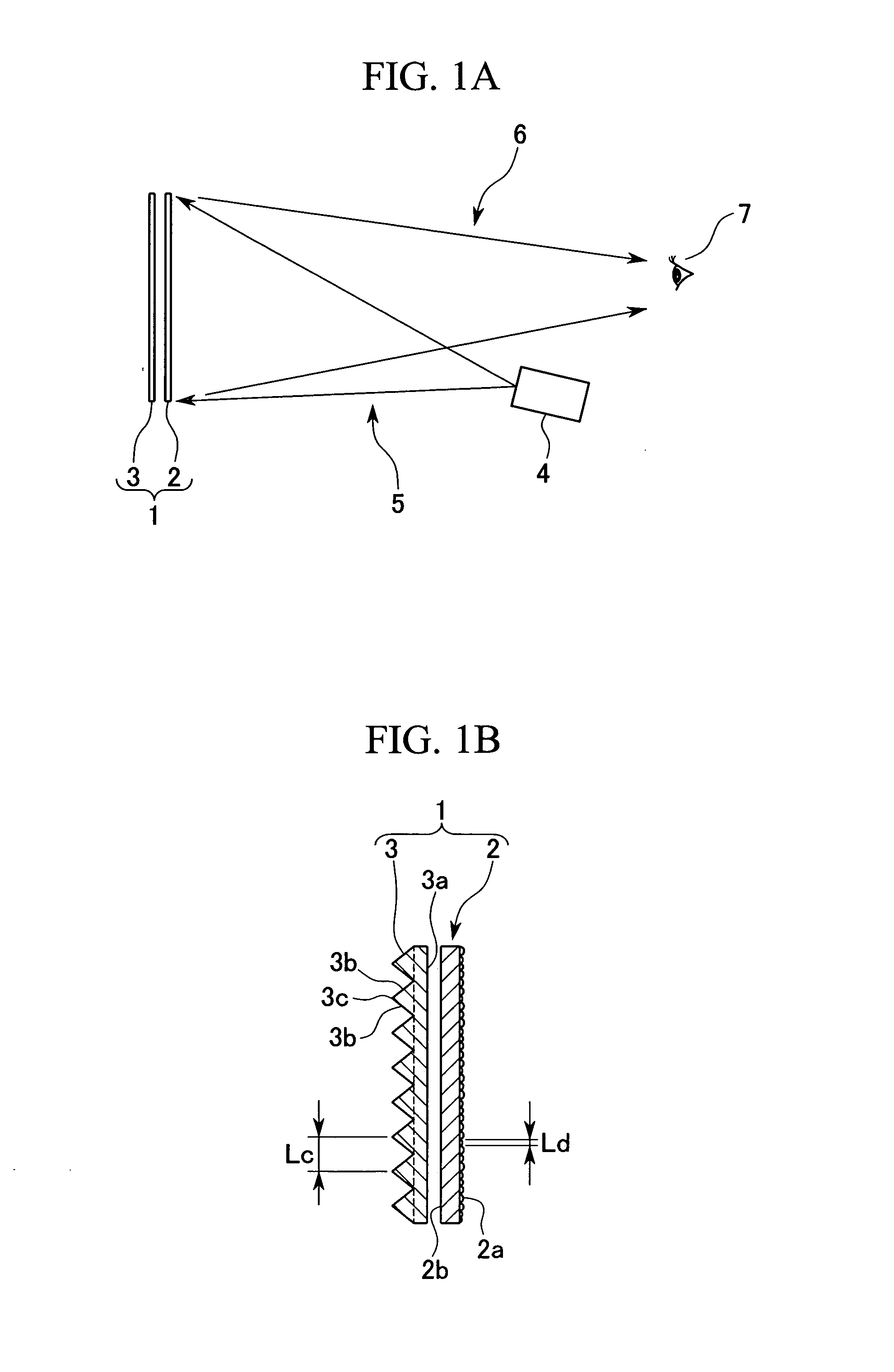
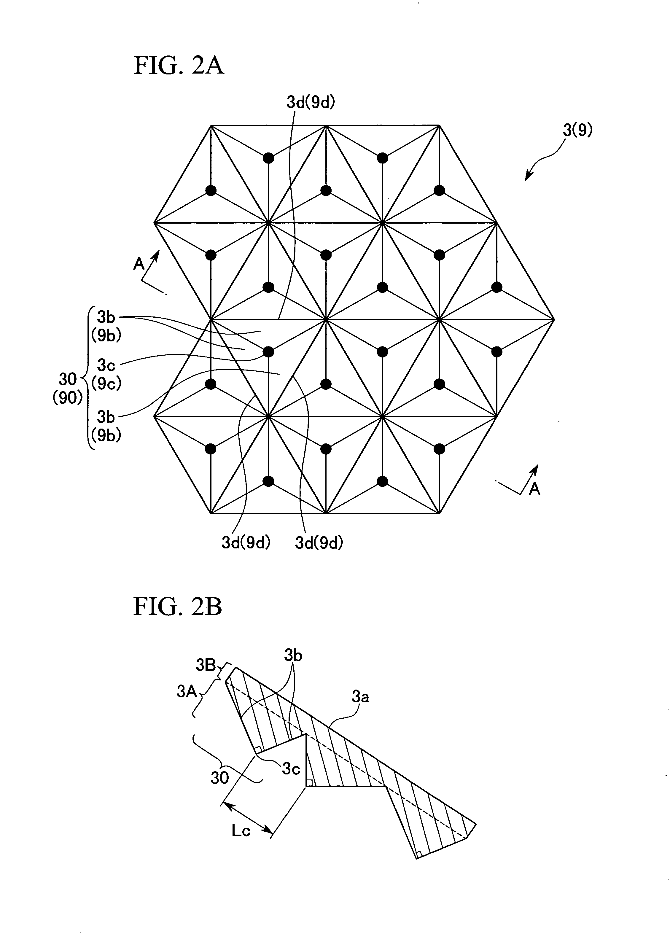
[0227]FIG. 9A shows a schematic plane view for describing an outline structure of a front projector system according to the second embodiment of the present invention. FIG. 9B shows a schematic view of a-a section (b-b section, c-c section) in FIG. 9A. FIG. 10 shows a schematic front view for describing a structure of a reflection screen used in the front projector system according to the second embodiment of the present invention.

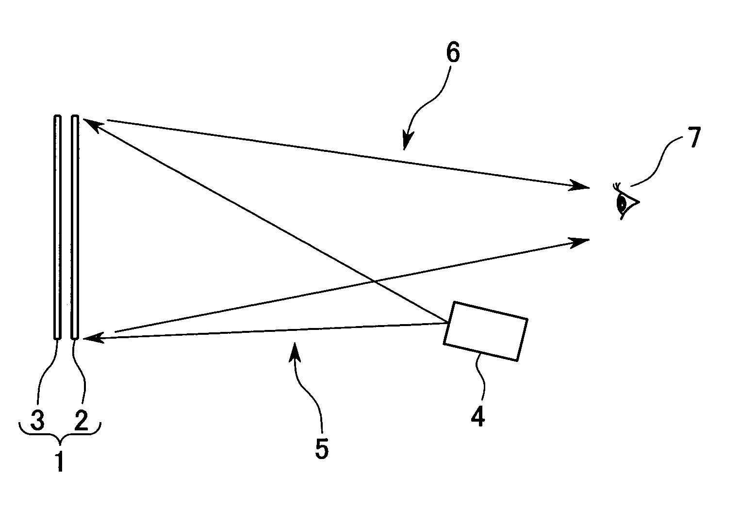
[0228] A projector system (front projector system) 100 according to the present embodiment projects a plurality of images on the reflection screen and is capable of projecting only one of the images on respective viewing regions which are independent of one another.

[0229] As shown in FIG. 9A, the front projector system 100 comprises projectors 4A, 4B, and 4C and the plate shaped reflection screen 1 which is supported by a scree...

third embodiment

[0269] A description will proceed of a front projector system according to a third embodiment of the present invention.

[0270]FIG. 12 shows a schematic plane view for describing an outline structure of the front projector system according to the third embodiment of the present invention. A projector system (front projector system) 101 according to the third embodiment comprises a reflection screen 102 instead of the reflection screen 1 used in the projector system 100 described in the second embodiment. The projector system 101 comprises the projectors 4A and 4C which are similar in structure to the second embodiment. In the example being illustrated, the projector 4A projects the projection light 5A in the range in which the projection light 5A is overlapped with the projection light 5C, with the incident angle θ. The projector 4C projects the projection light 5C in a direction having output angle θ in which the projection light 5A is outputted. A description will be mainly made as...

fourth embodiment

[0304] A description will proceed to a multi-vision projector system according to a fourth embodiment of the present invention.

[0305]FIG. 13A shows a schematic plane view for describing an outline structure of a multi-vision projector system according to the fourth embodiment of the present invention. FIG. 13B shows a schematic view of a-a section (b-b section, c-c section) of FIG. 13A. Incidentally, it is possible to use the reflection screen illustrated in any one of FIG. 1 and FIG. 10 as a reflection screen used in the multi-vision projector system according to the fourth embodiment of the present invention.

[0306] In the projector system (multi-vision projector system) 100 according to the present embodiment, a plurality of images are projected on the reflection screen and the images are capable of being viewed on a plurality of viewing regions which are independent of one another.

[0307] As shown in FIG. 13A, the projector system 100 comprises projectors 4A, 4B, and 4C, a flat...


PUM


Abstract

A reflection type projecting screen includes a diffuse plate having a diffuse transmission surface for converting at least transmission light into diffused light and a corner cube array for reflecting the light passing through the diffuse plate to a position which is approximately similar to a passing position of the diffuse transmission surface. The diffuse plate and the corner cube array are positioned in an order of the diffuse plate and the corner cube array. The reflection screen is capable of improving utilization efficiency of light and simplifying the structure while reducing the effect of outside light. Furthermore, there are provided a front projector system and a multi-vision projector system each of which has a projector for projecting the projection light and a reflection screen for reflecting the projection light as diffused light having directivity in at least one predetermined direction, in accordance with the incident direction of the projection light.

Description

BACKGROUND OF THE INVENTION [0001] 1. Field of the Invention [0002] Priority is claimed on Japanese Patent application No. 2004-336345, filed Nov. 19, 2004, No. 2004-343160, filed Nov. 26, 2004, and No. 2004-343161, filed Nov. 26, 2004, the contents of which are incorporated herein by reference. [0003] The present invention relates to a reflection type projecting screen, and more particularly, to a reflection type projecting screen capable of being preferably used in a front projector system or the like which reflects projection light projected from a cine-projector, a projector, or the like which is positioned at a viewing side, in order to view an image. In addition, the present invention relates to a front projector system using a reflection type projecting screen. Furthermore, the present invention relates to a multi-vision projector system, and more particularly, to a multi-vision projector system in which it is possible for a plurality of viewers to appreciate images different...

Claims


Application Information

Patent Timeline
Patent Type & Authority Applications(United States)
IPC IPC(8): G03B21/56
CPCG03B21/10G03B21/602
Inventor GOTO, HISASHI
Owner OLYMPUS CORP
Why Eureka
Try Eureka