Lighted bollard

Inactive Publication Date: 2006-05-25
LEADER MFG
View PDF19 Cites 53 Cited by
  • Summary
  • Abstract
  • Description
  • Claims
  • Application Information

AI Technical Summary

Benefits of technology

[0006] Accordingly, the present invention provides a lighted post that can be assembled in a manner to reduce or min

Problems solved by technology

However, the light sources used in conventional lighted posts produce a significant amount of heat and, further, consume a considerable amount of energy.
If the light sources are energized for a significant length of time the housing may become q

Method used


Image

  • Lighted bollard
  • Lighted bollard
  • Lighted bollard

Examples


Example

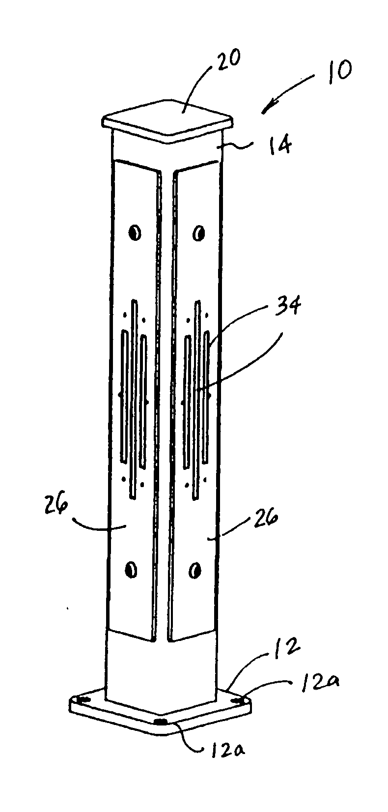
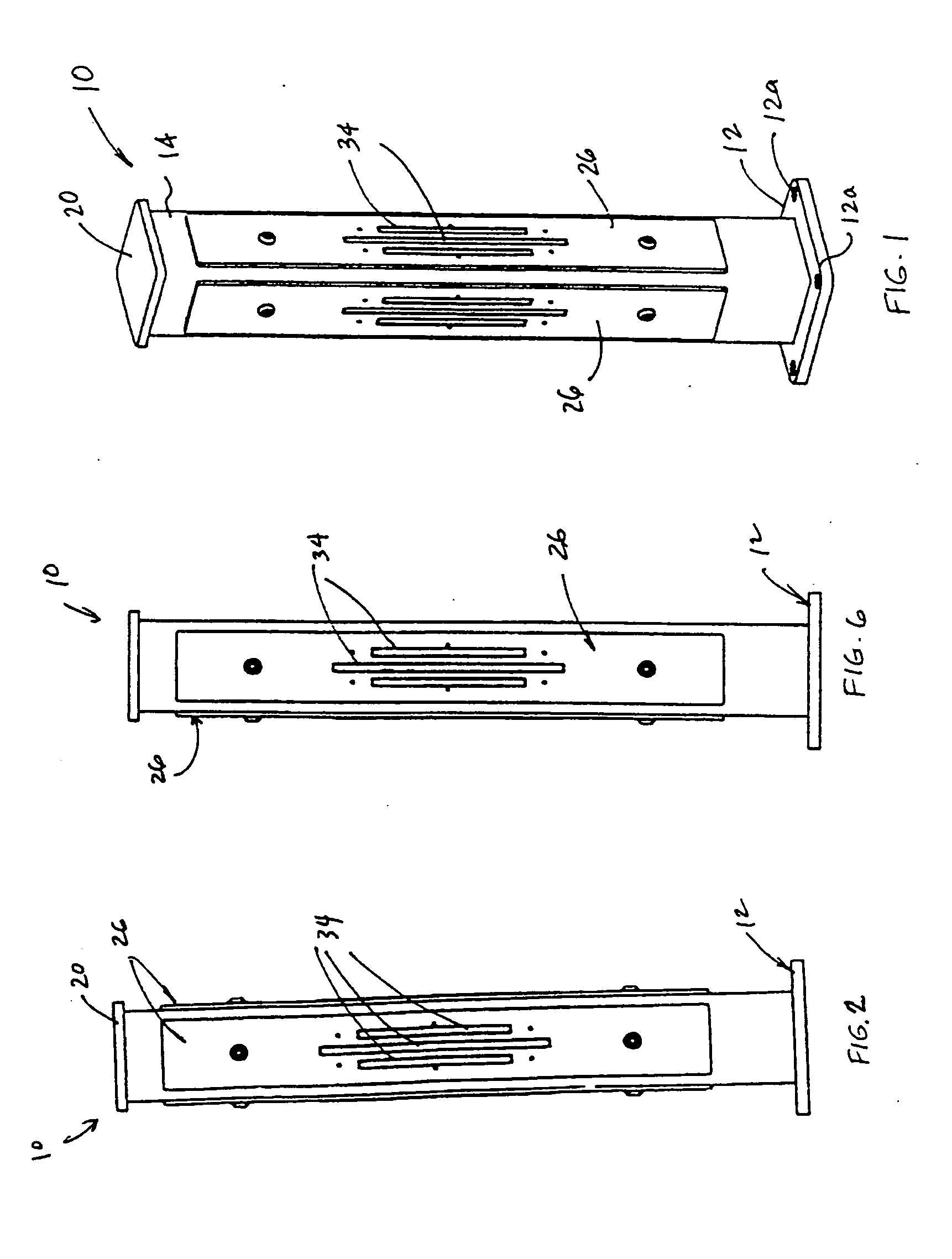
[0165] Referring to FIG. 1, the numeral 10 generally designates a lighted post of the present invention. As will be more fully described below, lighted post 10 is particularly useful as a lighted bollard and incorporates the use of light assemblies that use less energy and produce less heat than the lights used in conventional bollards and, further, in a manner to limit the intrusion of bugs and dirt into the post to maintain the aesthetic appearance of the lighted post.

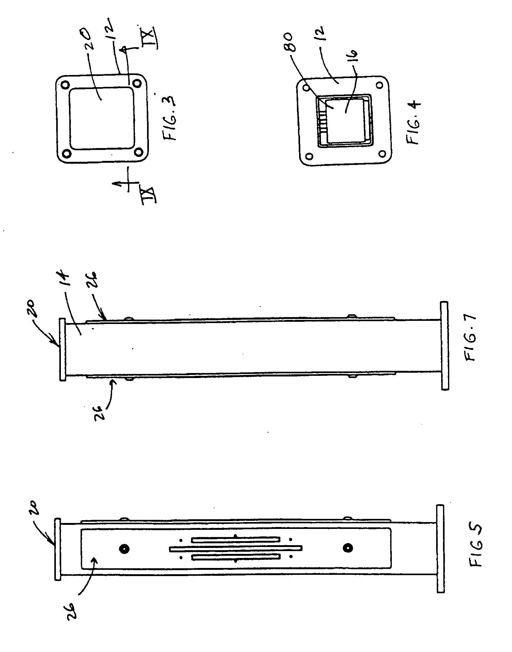
[0166] In the illustrated embodiment, lighted post 10 includes a base 12 and a tubular member 14 that is mounted to base 12 to form a stanchion. It should be understood that the stanchion may be assembled from a variety of other components and further may not require a base. Base 12 is adapted to anchor tubular member 14, for example, to a rigid support surface, such as the ground or to a mat, such as a concrete or asphalt pad or a deck. As best seen in FIG. 1, base 12 includes a plurality of mounting openings 12a f...


PUM


Abstract

A lighted post includes a stanchion and a light assembly. The light assembly includes a body, with a light emitting surface, and a light source that is coupled to the body. The light assembly is adapted for coupling to a power source for powering the light source. When powered light from the light source is directed into the body and is directed from the body through the light emitting surface. The light assembly is mounted to the stanchion, with the body being located in a light transmitting opening provided in the stanchion, such that the light emitting surface faces outwardly from the stanchion to thereby direct light outwardly from the stanchion.

Description

CROSS REFERENCES TO RELATED APPLICATIONS [0001] This application is related to and claims the benefit of provisional applications entitled LIGHTED POST ASSEMBLY, Ser. Nos. 60 / 631,017; 60 / 631,132; 60 / 655,160, filed Nov. 24, 2004; Nov. 26, 2004; and Feb. 22, 2005, respectively (Attorney Docket Nos. LEA03 P-303, LEA03 P-303A, and LEA03 P-303B), which are herein incorporated by reference in their entireties.TECHNICAL FIELD AND BACKGROUND OF THE INVENTION [0002] The present invention generally relates to lighted posts and, more particularly, to lighted posts that may be used as bollards or pathway lights. [0003] Lighted posts have been used for years to light the entrance way of a building or a residence or to light an area, such as a walkway or deck, including a pool deck. Most residential lights are formed from a support post and a housing that is mounted to the post. The housing typically houses one or more lights, such as halogen lights or the like, and incorporates light transmittin...

Claims


Application Information

Patent Timeline
IPC IPC(8): F21S13/10
CPCE01F9/0165F21S8/083F21S9/02F21W2111/023F21W2111/04F21W2131/10F21Y2101/02E01F9/617F21Y2115/10
Inventor FLAHERTY, RICHARD A.GRAY, MATTHEW A.COFFEY, MICHAEL P.
Owner LEADER MFG
Why Eureka
Try Eureka