
Method for recognizing projection views of radiographs

a radiograph and projection view technology, applied in the field of radiograph processing, can solve the problems of difficult computer-based analysis procedures, time-consuming manual generation of template images, and difficulty in recognizing the projection view of radiographs, so as to promote efficiency, speed up the recognition process, and promote robustness.

Active Publication Date: 2006-05-25
CARESTREAM HEALTH INC
View PDF4 Cites 25 Cited by
  • Summary
  • Abstract
  • Description
  • Claims
  • Application Information

AI Technical Summary

Benefits of technology

[0012] According to the present invention, this objective is achieved by the following steps: correcting the orientation of the radiograph, extracting a region of interest from the radiograph, and recognizing the projection view of radiograph. In addition, pre-processing the input radiograph can be accomplished.
[0017] The present invention provides some advantages. For example, features of the method promote robustness. Preprocessing of radiographs helps avoid the interference from the collimation areas and other noise. In addition, features used for orientation classification are invariant to size, translation and rotation. Features of the method also promote efficiency. For example, the processes can be implemented on a sub-sampled coarse resolution image, which greatly speeds up the recognition process.

Problems solved by technology

However, recognizing the projection view of radiographs is a challenging problem as radiographs are often taken under a variety of examination condition.
However all these analysis procedures are difficult for computer to achieve in a similar fashion due to the limitation of the image analysis algorithms.
However, the manual generation of these template images is quite time consuming, and more particularly, it is highly observer dependent, which may introduce error into the classification.
In both methods, no preprocessing is implemented to reduce the influence of irrelevant and often distracting data.
For example, the unexposed regions caused by the blocking of the x-ray collimator during the exposure may result in a significant white borders surrounding the image.
Applicants have noted that if such regions are not removed in a pre-processing step and therefore used in the computation of similarity measures, the classification results can be seriously biased.
However, the color information is not available in radiographs.
Therefore these methods are not directly suitable for radiograph projection view recognition.

Method used


Image

  • Method for recognizing projection views of radiographs
  • Method for recognizing projection views of radiographs
  • Method for recognizing projection views of radiographs

Examples


Embodiment Construction

[0025] The following is a detailed description of the preferred embodiments of the invention, reference being made to the drawings in which the same reference numerals identify the same elements of structure in each of the several figures.

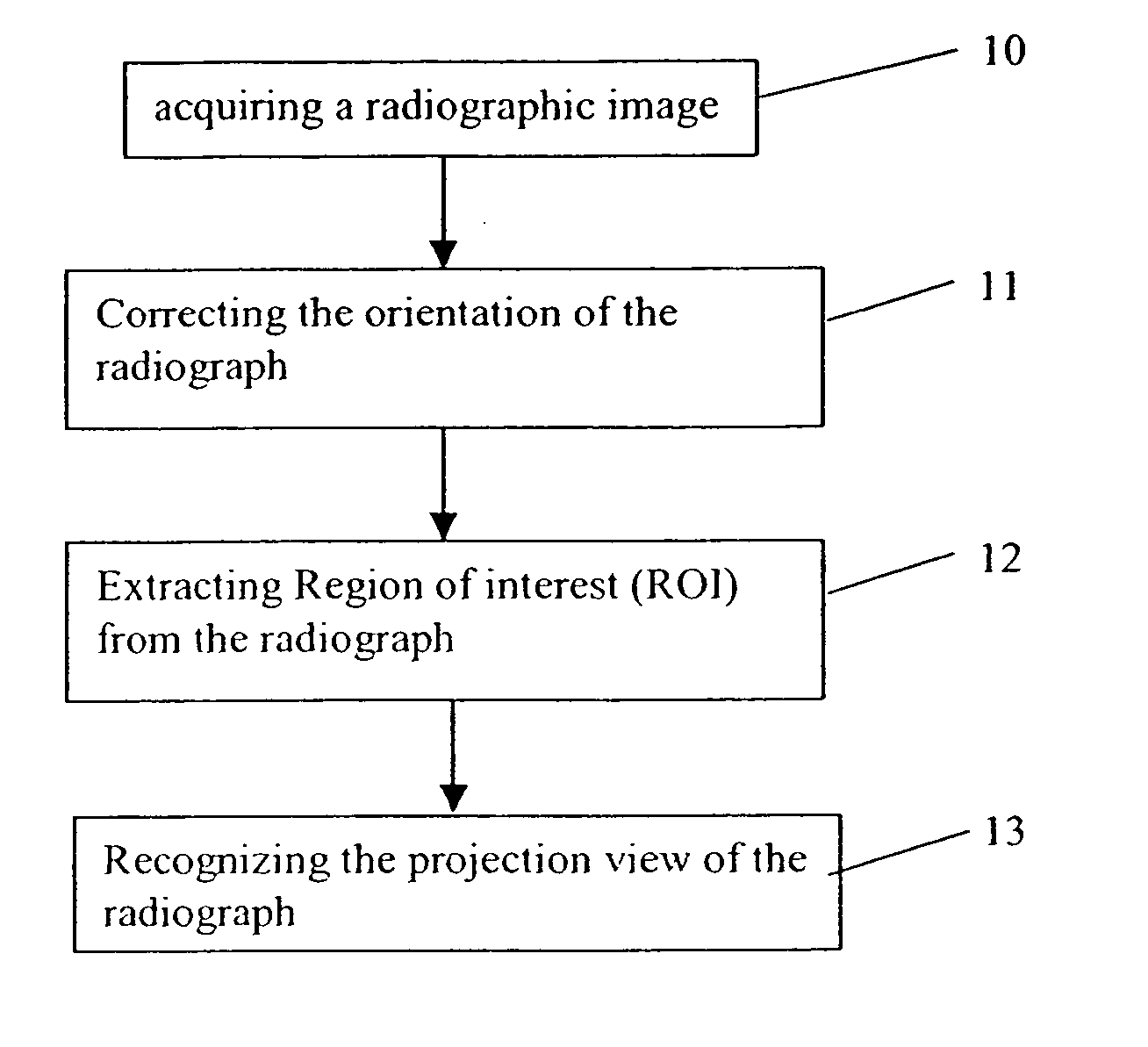
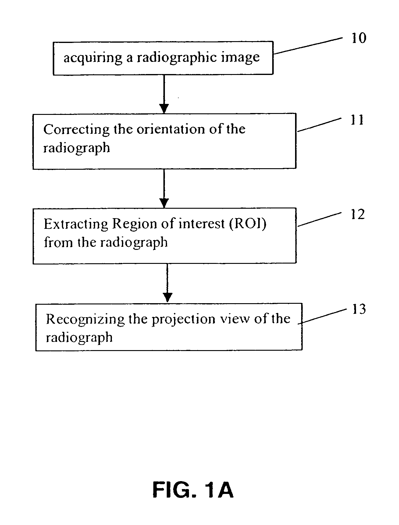
[0026] The present invention discloses a method for automatically recognizing the projection view of radiographs. A flow chart of a method in accordance with the present invention is shown in FIG. 1A. As shown in FIG. 1A, the method includes three stages: correcting the orientation of radiograph (step 11); extracting a Region of Interest (ROI) from the input radiograph (step 12); and recognizing the projection view of the radiograph (step 13).

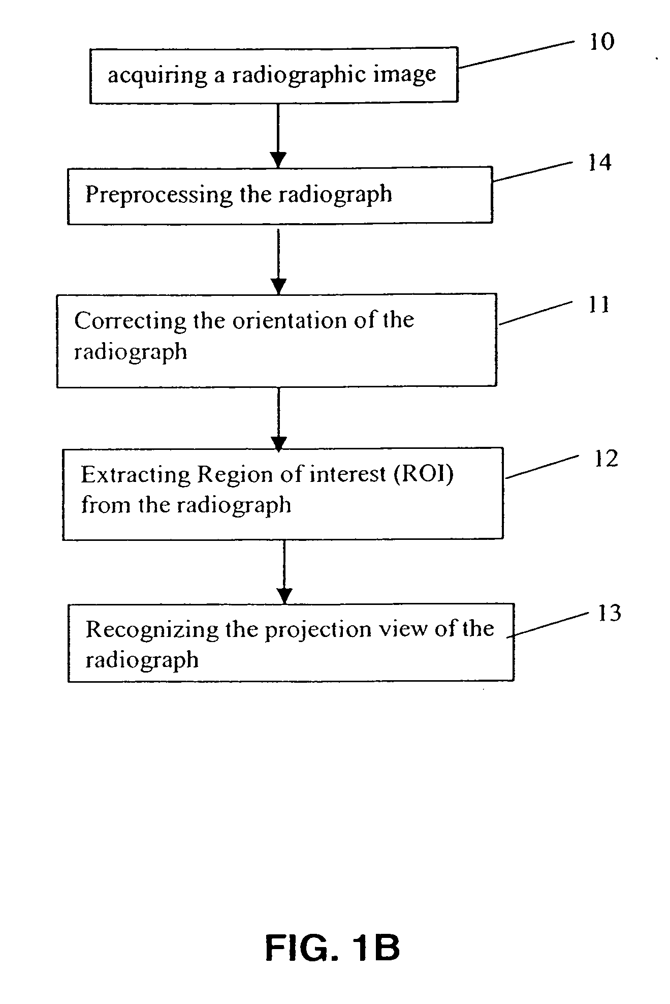
[0027] In a further embodiment of the present invention, shown in the flow chart of FIG. 1B, an additional step can be applied prior to the image orientation correction. This additional step (step 14) is the preprocessing of radiographs, and will be more particularly described below.

[0028] In a still furthe...


PUM


Abstract

A method for recognizing the projection view of radiographs comprising the steps of correcting the orientation of the input radiograph, locating a region of interesting in the radiograph, recognizing the projection view of the radiograph.

Description

CROSS REFERENCE TO RELATED APPLICATIONS [0001] Reference is made to, and priority is claimed from, U.S. Provisional Application No. 60,630,287, entitled “METHOD FOR RECOGNIZING PROJECTION VIEWS OF RADIOGRAPHS”, filed on Nov. 23, 2004 in the names of Luo et al, and which is assigned to the assignee of this application, and incorporated herein by reference. [0002] Reference is further made to commonly assigned application U.S. Provisional Application No. 60 / 630,286, entitled “AUTOMATED RADIOGRAPH CLASSIFICATION USING ANATOMY INFORMATION”, provisionally filed on Nov. 23, 2004 in the names of Luo et al, and which is assigned to the assignee of this application, and incorporated herein by reference. [0003] Reference is further made to commonly assigned application U.S. Provisional Application No. 60 / 630,270, entitled “METHOD FOR AUTOMATIC SHAPE CLASSIFICATION”, provisionally filed on Nov. 23, 2004 in the name of Luo, and which is assigned to the assignee of this application, and incorpor...

Claims


Application Information

Patent Timeline
IPC IPC(8): G06K9/00G06K9/62
CPCG06K9/00G06K2209/05G06T7/0012G06T7/0042G06T2207/30008G06T7/73G06V2201/03
Inventor LUO, HUILUO, JIEBO
Owner CARESTREAM HEALTH INC
Learn More