Vehicle control device

a control device and vehicle technology, applied in the direction of machines/engines, transportation and packaging, road transportation, etc., can solve the problems of decreasing braking force, increasing and decreasing deceleration, etc., to prevent the occupant(s) from feeling uncomfortable, reducing energy loss, and reducing physical impa

Inactive Publication Date: 2006-05-25
TOYOTA JIDOSHA KK
View PDF6 Cites 9 Cited by
  • Summary
  • Abstract
  • Description
  • Claims
  • Application Information

AI Technical Summary

Benefits of technology

[0009] The present invention contemplates a vehicle control device that can minimize physical impact experienced by the vehicle's occupant(s) and also decelerate the vehicle while preventing the occupant(s) from feeling uncomfortable. The present invention also contemplates a vehicle control device providing reduced energy loss.
[0010] The present invention in one aspect provides a vehicle control device controlling a vehicle including a drive source and a transmission linked to the drive source. The present vehicle control device includes: an applier applying braking force to the vehicle; an acceleration pedal position detector detecting an acceleration pedal position; a downshift detector detecting whether the transmission has completely downshifted; and a controller controlling the applier to apply the braking force for the acceleration pedal position smaller than a predetermined position in angle, and reduce the braking force when the transmission has completely downshifted.
[0011] In accordance with the present invention when an accelerator pedal position is smaller than a predetermined position in angle and the vehicle is coasting, and the transmission also downshifts, then after the transmission has completely downshifted, braking force is reduced. Thus by the reduced braking force a difference in braking force between the downshift is reduced. This can reduce physical impact attributed to downshifting. Furthermore if an accelerator pedal position is smaller than the predetermined position in angle the vehicle is coasting the braking force applied by the applier is not reduced at a timing other than that of downshifting. This can prevent deceleration from increasing and decreasing for the same gear. The vehicle can thus be decelerated while the vehicle's occupant(s) do(es) not feel uncomfortable. The present vehicle control device can thus reduce physical impact experienced by the occupant(s) and also decelerate the vehicle without causing the occupant(s) to feel uncomfortable.
[0013] In accordance with the present invention for an accelerator pedal position smaller than the predetermined position in angle the applier applies braking force increased at a predetermined variation rate. Thus the vehicle can gradually be decelerated and thus prevented from rapidly decelerating.
[0015] In accordance with the present invention a power generator can generate power while the power generator's load can be increased and decreased to adjust the vehicle's braking force. Thus, braking force can be applied while kinetic energy can be recovered effectively as an electrical energy. The present vehicle control device can thus reduce energy loss.
[0019] In accordance with the present invention a throttle valve can have its angle increased and decreased to open and close to increase and decrease pumping loss and adjust the vehicle's braking force.

Problems solved by technology

As disclosed in the publication, however, after the transmission has completely downshifted the brake control device resumes to apply braking force as applied before the transmission starts to downshift, and decrements the braking force.
As such, the engine braking increased by downshifting and the braking force applied by the braking force application controller cause a relatively large deceleration.
Accordingly the vehicle's occupant(s) feels / feel physical impact, and furthermore, as the completion of the downshift is followed by decrementing an amount of braking force applied, despite the downshift, reduced braking force is provided, and after the downshift when a prediction is made that the transmission again downshifts, incremented deceleration is provided, so that despite the same transmission gear, deceleration is increased and decreased and the occupant(s) may feel uncomfortable.

Method used


Image

  • Vehicle control device
  • Vehicle control device
  • Vehicle control device

Examples


Embodiment Construction

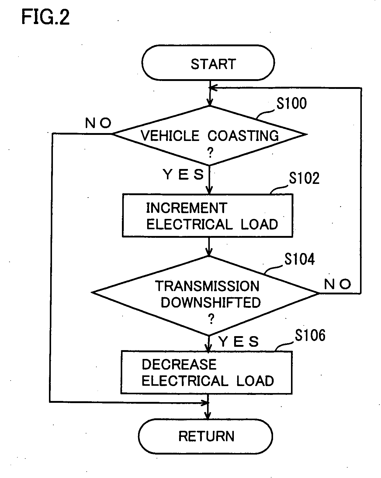
[0024] Hereinafter reference will be made to the drawings to describe the present invention in an embodiment. In the following description, identical components are dented by identical reference characters. They are also identical in function and name.

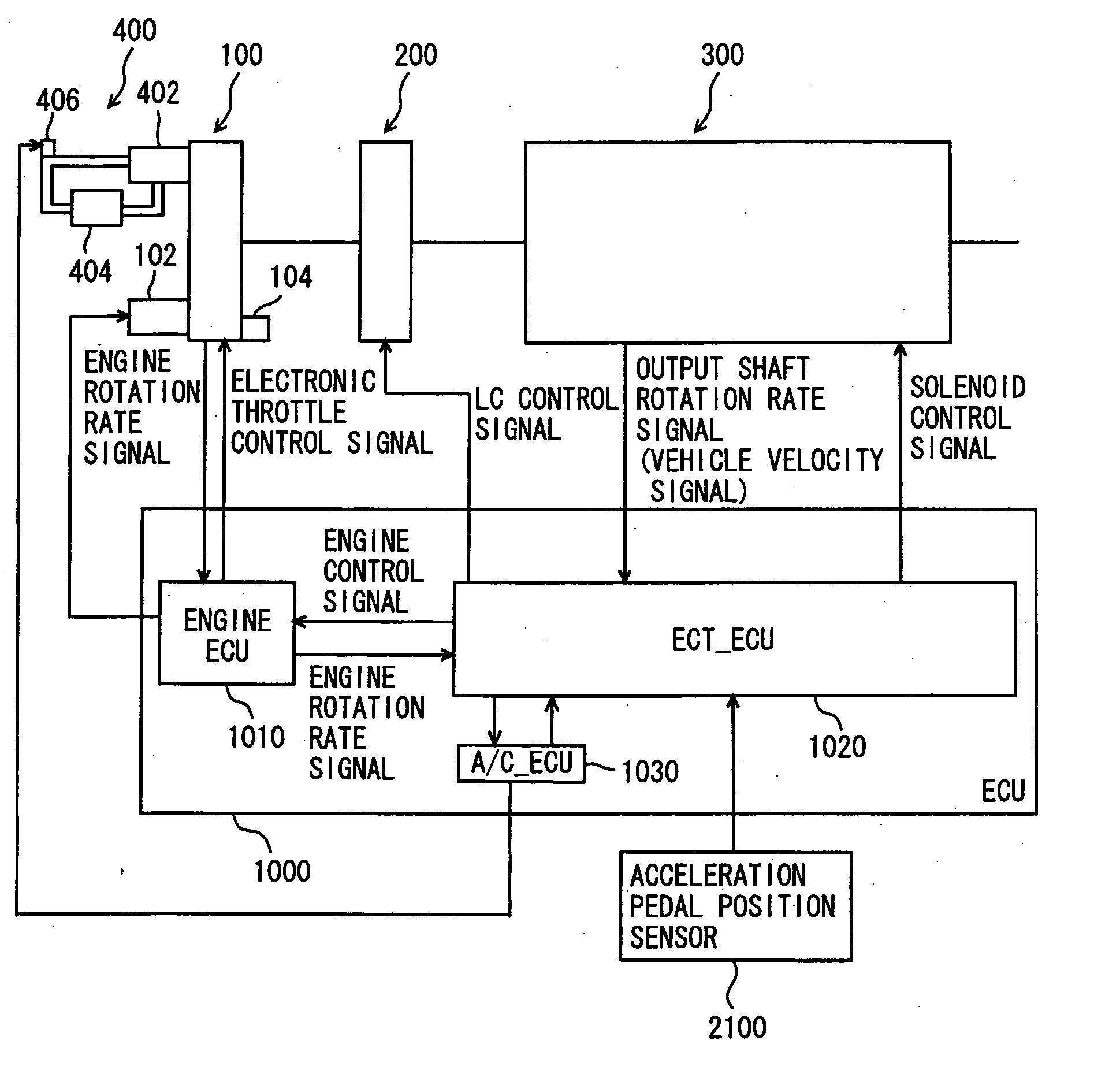
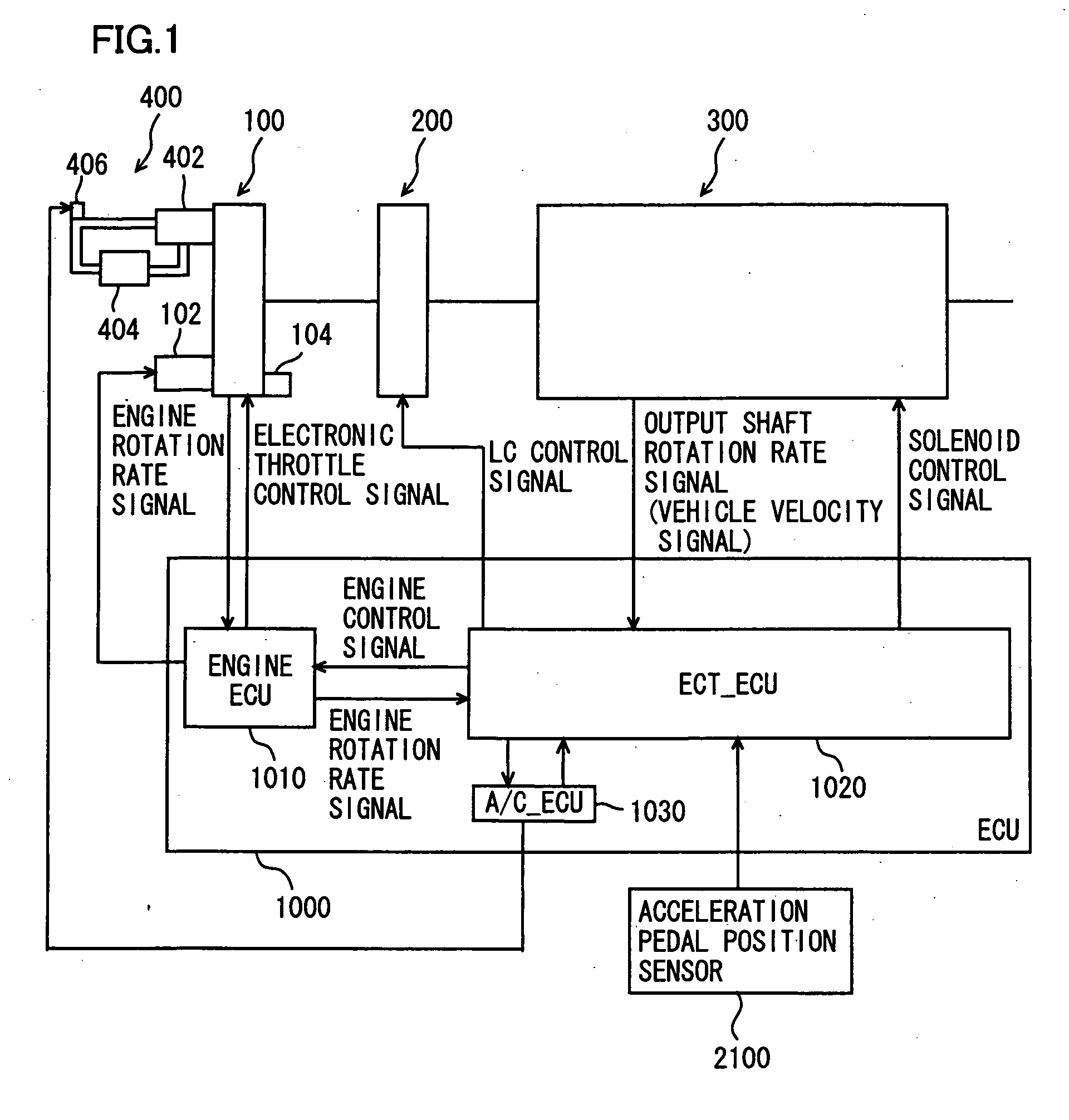
[0025] Reference will initially be made to FIG. 1 to describe a powertrain of a vehicle including a control device of the present embodiment. The present embodiment provides a vehicle control device implemented by a program executed by an electronic control unit (ECU) 1000 shown in FIG. 1. In the present embodiment an automatic transmission will be described as that having a gear transmission mechanism including a fluid coupling implemented by a torque converter. Note that the present invention is not limited to that having a gear transmission mechanism. It may be a continuously variable transmission employing a belt. Furthermore the gear transmission mechanism may be configured of a planetary gear or may be a constantly engaged gear....


PUM


Abstract

An ECT_ECU executes a program including the steps of: when the vehicle is coasting, increasing at a predetermined variation rate an electrical load attributed to an alternator; and if the transmission has downshifted, reducing the electrical load attributed to alternator.

Description

[0001] This nonprovisional application is based on Japanese Patent Application No. 2004-336120 filed with the Japan Patent Office on Nov. 19, 2004, the entire content of which is hereby incorporated by reference. BACKGROUND OF THE INVENTION [0002] 1. Field of the Invention [0003] The present invention relates generally to technology employed to brake vehicles, and particularly to that employing auxiliary equipment to increase engine brake to brake vehicles. [0004] 2. Description of the Background Art [0005] An automatic transmission automatically shifting speed is conventionally known. When a vehicle having such an automatic transmission mounted thereon, and coasting with the accelerator off is decelerated, the transmission can downshift. If the transmission has downshifted, and the current speed is shifted, the engine thereafter has an increased rate of rotation, and engine brake contributes to increased braking force. This changes deceleration between before and after the current ...

Claims


Application Information

Patent Timeline
Patent Type & Authority Applications(United States)
IPC IPC(8): B60K41/20B60W10/00B60W10/04B60W10/06B60W10/30B60W30/19B60W30/20F02D29/00
CPCB60T7/12B60W10/08B60W10/11Y10T477/644B60W30/18109Y10T477/82Y10T477/81B60W10/30Y02T10/60
Inventor OGAWA, HIROYUKIHARADA, YOSHIHARUYUKI, ATSUSHI
Owner TOYOTA JIDOSHA KK
Why Eureka
Try Eureka