Computer workstation resource usage monitoring system

a technology for monitoring system and workstation resource usage, applied in the direction of digital computers, error detection/correction, instruments, etc., can solve the problems of not being able to effectively determine not having a solution that allows for effective determining the usage of workstation resources, and being more likely to have non-homogeneous software and hardware components

Inactive Publication Date: 2006-05-25
SCHNEIDER JOHN ROGER
View PDF11 Cites 45 Cited by
  • Summary
  • Abstract
  • Description
  • Claims
  • Application Information

AI Technical Summary

Benefits of technology

[0012] The centralized computer system stores and aggregates the resource usage data and component data from computer workstations. It also houses data pertaining to known hardware and software performance based on specific hardware/software configurations. When enough data is collected

Problems solved by technology

Management of computer workstation resource usage is typically not done due to the complexities involved.
There is no solution that allows for effectively determining usage of a workstation and analyzing if that usage constitutes the need for a complete replacement, an upgrade of a hardware component (e.g. memory) or software component (e.g. operating system), or no action at all.
Conversely, computer workstations are typically used only during normal working days and hours, may be connected and disconnected from the network frequently, and are much more likely to have non-homogeneous software and hardware components.
This makes it difficult to determine what level of usage the computer workstation experiences.
This has limited use, as a failure usually prompts the user of the system to notify someone of the problem.
This continuous monitoring, especially when aggregated over time, can use a significant portion of the computer systems' resources, itself becoming a resource drain.
Conventional systems do not contain software distribution system function

Method used


Image

  • Computer workstation resource usage monitoring system
  • Computer workstation resource usage monitoring system
  • Computer workstation resource usage monitoring system

Examples


Embodiment Construction

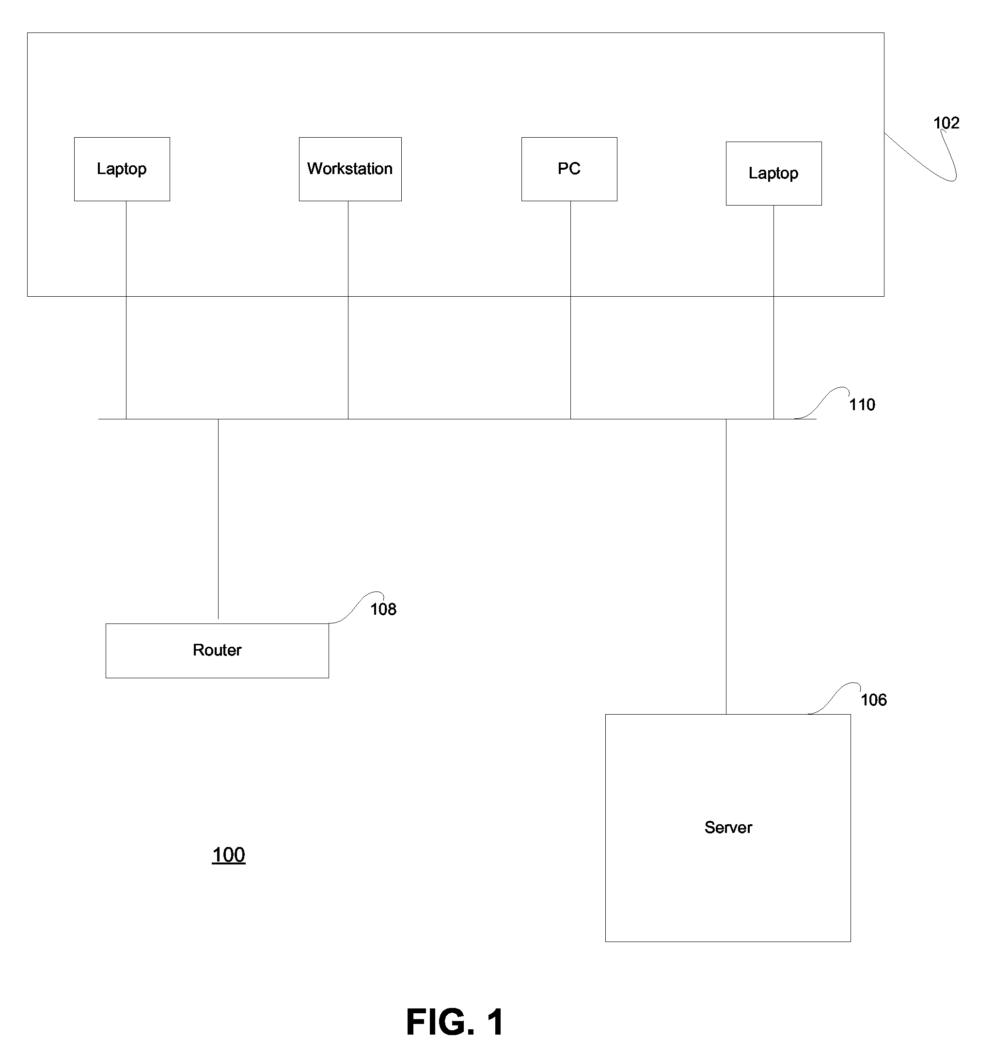
[0023]FIG. 1 illustrates a computer network in conjunction with which embodiments of the invention can be practiced. The description of FIG. 1 is intended to provide a general description of a suitable networked environment within which the invention can be implemented. This is a single, exemplary embodiment, and those skilled in the art will recognize that there are many variations to computer networks that the invention could be put to use in.

[0024]FIG. 1 shows a computer network 100. The computer network 100 has a bus 110 with which different nodes of the network are connected. In one embodiment, the bus 110 could be Ethernet cabling. Other possibilities could include fiber, twisted pair copper wire, or the Internet. In addition, the network could be comprised of wireless connections wherein the bus 110 becomes airwaves.

[0025] A plurality of different computer workstations 102 are connected to the bus 110. In this embodiment, these workstations include laptops and desktops (PCs...


PUM


Abstract

A configurable computer resource usage system for collecting hardware and software usage from computer systems with various operating systems, aggregating and filtering the data, transferring it to a centralized computer system, and performing analysis to determine if a hardware or software upgrade is needed. A computer software product that executes on a client computer workstation and collects performance data relevant to that specific machine and data indicating the versions of software and hardware components installed on that machine. A centralized computer that receives the performance and versioning data, stores it, aggregates it with other static data, and performs analysis to determine if the client computer is an upgrade candidate. A graphical user interface displaying the analysis and relevant summarized data is provided through one of several methods, including a web browser accessing the data over the Internet or LAN or WAN.

Description

FIELD OF THE INVENTION [0001] The present invention relates to determining the usage of a plurality of computer systems, analyzing the usage, and on-demand viewing of the analysis to determine if an upgrade is warranted. RELATED ART [0002] Computer system networks typically have many workstations (PCs or laptops) attached and running on them, possibly using different operating systems. The workstations will be configured with different hardware and software components depending on several items, including when the workstation was purchased, the expected type of usage of the workstation, and the amount of capital available for the initial purchase. [0003] Management of computer workstation resource usage is typically not done due to the complexities involved. Instead, computer workstations are usually managed through a replacement cycle process. The standard cycle is usually to replace a computer workstation with an entirely new machine every three years. There is no solution that al...

Claims


Application Information

Patent Timeline
IPC IPC(8): G06F9/44
CPCG06F11/3442G06F11/3476G06F11/3495G06F2201/875
Inventor SCHNEIDER, JOHN ROGER
Owner SCHNEIDER JOHN ROGER
Why Eureka
Try Eureka