
Device for punching blanks out of a flat sheet

a flat sheet, punching technology, applied in the direction of paper/cardboard containers, containers, container making machinery, etc., can solve the problems of high wedge force, destroying supporting points, and profiled strips having to be removed, so as to achieve easy removal and replacement, and rapid replacement with other strip types

Inactive Publication Date: 2006-06-01
VOSSEN FRANZ
View PDF11 Cites 20 Cited by
  • Summary
  • Abstract
  • Description
  • Claims
  • Application Information

AI Technical Summary

Benefits of technology

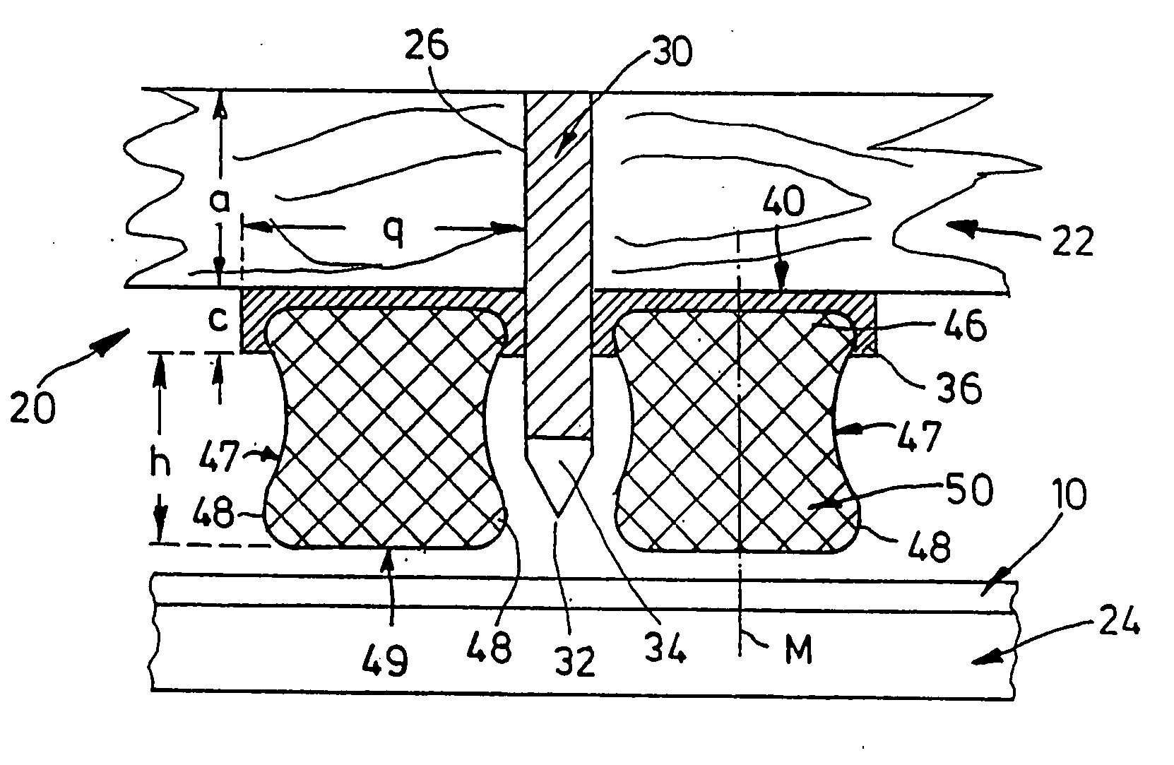
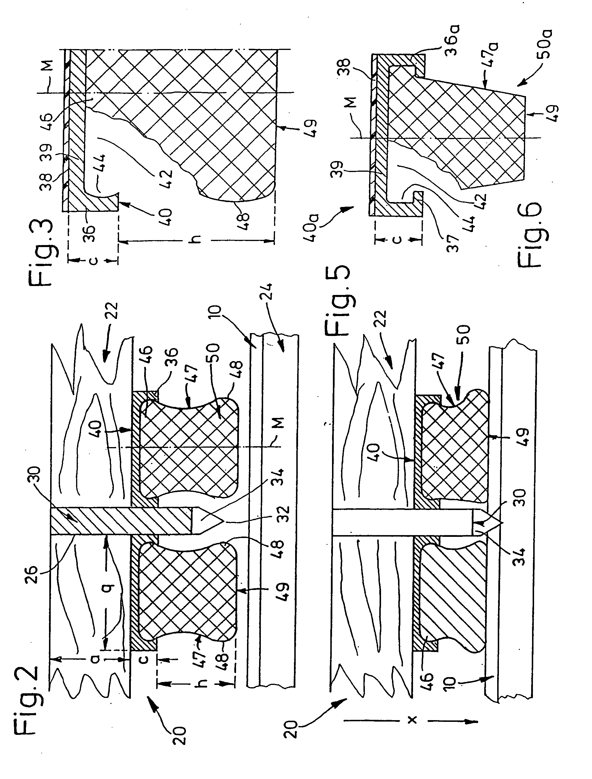
[0007] According to the invention, a channel-like profile consisting of rigid material is arranged on the carrier plate parallel to the punching tool on each of the longitudinal sides thereof, and the profiled strip is inserted with the ridge region of its cross section into said channel-like profile; it is therefore not directly connected to the carrier plate, said carrier plate preferably being formed of a multilayer plywood plate. To this end, it has proven to be advantageous to accommodate the profiled strip in the rail-type channel profile in a form-fitting manner, so that it can be removed without damage.
[0013] It is ideal if the profiled strip completely fulfils its function during the punching operation and nevertheless is easy to remove and replace. This is ensured by the above-described rail in the form of a channel profile which is adhesively bonded to the wood of the punching die; this also secures the position of the profiled strip which consists of rubber or a similar elastic material. Moreover, rapid replacement with other strip types is readily possible, for example with a softer rubber.

Problems solved by technology

When the cutting lines penetrate into the sheet material, very high wedge forces develop which try to destroy the supporting points.
One disadvantage of systems known to date is that the profiled strip has to be removed in the event of tool repairs or when forming supporting points.
This is difficult in particular since the wood breaks open and profiled parts remain on the wood, and this necessitates cleaning of the surface.
Moreover, the base of the profiled strip is lost and the new profiled strips must be inserted, wherein the curing time of the adhesive gives rise to a downtime of the machine.

Method used


Image

  • Device for punching blanks out of a flat sheet
  • Device for punching blanks out of a flat sheet
  • Device for punching blanks out of a flat sheet

Examples


Embodiment Construction

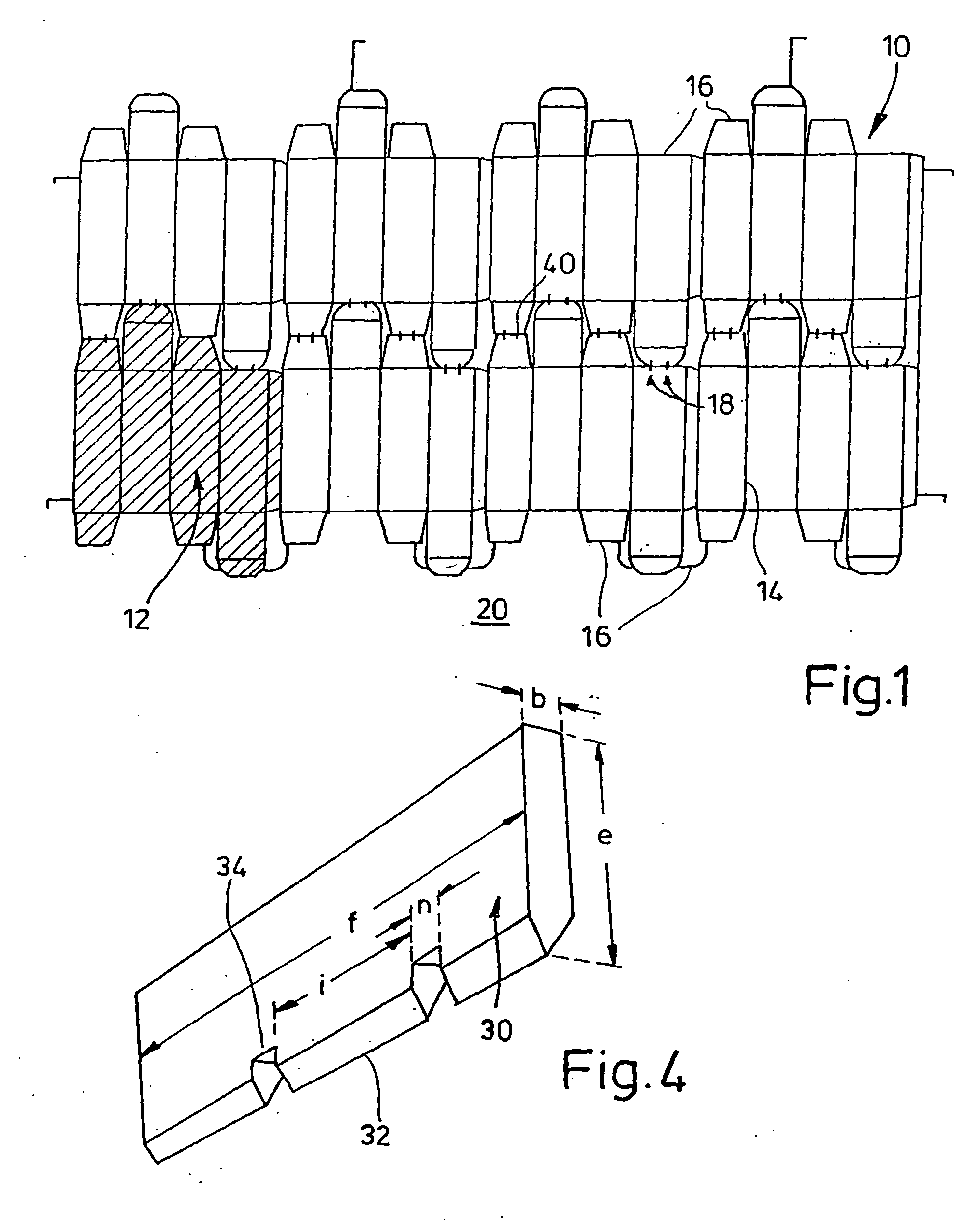
[0020] In order to punch packagings out of cardboard or corrugated cardboard, a sheet 10 of this material is fed for example to a flat bed punching machine; the sheet 10 exhibits the contours of eight adjoining blanks 12 for folded box; through these blanks 12, cyclic punching operations are to be carried out and have scoring lines 14—which define the subsequent folding operation—and also cutting lines 16 as cutting contours which define the outside. Adjacent cutting lines 16 are connected by pairs of so-called supporting points 18; the latter are necessary for further transporting the punched sheet 10 in the punching machine 20.

[0021] During processing thereof, the cardboard or corrugated cardboard sheet 10 lies on a punching plate 24 below a carrier plate 22 of thickness a of the punching machine 20, as shown in FIG. 2. The carrier plate 22 consists of a multilayer plywood plate 22, in which laser cuts 26 have been made in an arrangement which corresponds to the contours of the i...


PUM

PropertyMeasurementUnit
Flexibilityaaaaaaaaaa
Adhesivityaaaaaaaaaa
Distanceaaaaaaaaaa

Abstract

A device for punching blanks out of a flat sheet, in particular packaging blanks consisting of cardboard or corrugated cardboard, using a punching tool that is mounted in a carrier plate and projects beyond the plate in the form of a blade or cutting line, in addition to profiled strips, consisting of a material of limited flexibility, which flank the tool. A rail-type profiled channel consisting of a rigid material is located on the carrier plate, running parallel to the punching tool on each side of the longitudinal faces of the latter and one cross-sectional area of the profiled strip is inserted into the profiled channel in a positive fit. In addition, at least one lateral face of the cross-section of the profiled strip has a protuberant base.

Description

BACKGROUND OF THE INVENTION [0001] The invention relates to a device for punching blanks out of a flat sheet, in particular packaging blanks consisting of cardboard or corrugated cardboard, by means of a punching tool which is mounted in a carrier plate and projects beyond said plate in the form of a blade or cutting line, and also profiled strips consisting of a material of limited flexibility which flank said tool. [0002] Such devices, in which the tools made of steel strip slide along lateral profiled strips consisting of rubber or flexible plastic, are known in the packaging industry. These profiled strips are either adhesively bonded over their surface to the carrier plate—which is made of plywood for example—or are inserted by beads made in them into grooves of the carrier plate. Laser cuts are made in said plywood plate in order to accommodate so-called cutting lines. [0003] By virtue of this device, packaging blanks can be cut in groups out of a cardboard or corrugated cardb...

Claims


Application Information

Patent Timeline
IPC IPC(8): B26D7/02B26F1/40B26F1/44B31B50/20
CPCB26D7/025B26F1/40B26F1/44B31B1/20B31B2201/147B31B50/20Y10T83/2163Y10T83/06Y10T83/217Y10T83/7487Y10T83/2157Y10T83/2096
Inventor VOSSEN, FRANZ
Owner VOSSEN FRANZ
Learn More