Method of forming a recess structure, recessed channel type transistor and method of manufacturing the recessed channel type transistor

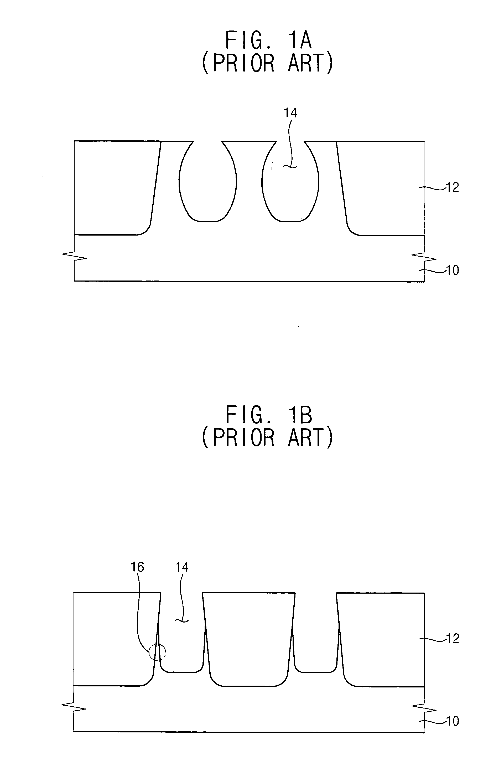
a technology of recess structure, which is applied in the direction of basic electric elements, electrical apparatus, semiconductor devices, etc., can solve the problems that gate trenches b>14/b> may not be advantageously employed for recessed channel type transistors having minute design rules, and the electrical characteristics of transistors deteriorate, etc., to achieve the effect of reducing junction leakage current, reducing width and increasing length

Inactive Publication Date: 2006-06-01
SAMSUNG ELECTRONICS CO LTD
View PDF12 Cites 93 Cited by
  • Summary
  • Abstract
  • Description
  • Claims
  • Application Information

AI Technical Summary

Benefits of technology

[0035] According to embodiments of the present invention, a recessed channel type transistor includes a gate electrode that has a lower portion partially buried in a substrate and enlarged with an elliptical shape, a track shape or a circular shape in accordance with a recess structure. Additionally, the recessed channel type transistor includes source / drain regions formed from an upper face of the substrate to a portion of the substrate where the gate electrode has a maximum width. Thus, a junction of the transistor may have a reduced width to thereby decrease junction leakage current from the junction. Further, the transistor may include a channel region having a greatly increased length in accordance with the enlarged gate electrode because the channel region is formed along the gate electrode. As a result, the recessed channel type transistor may have enhanced electrical characteristics and improved reliability.

Problems solved by technology

When the channel length of a transistor is less than an effective channel length of the transistor required for proper operation, a short channel effect may occur in the transistor which may deteriorate electrical characteristics of the transistor.
However, critical dimensions (CD) of the gate trenches 14 may become too large, so that these gate trenches 14 may not be advantageously employed for a recessed channel type transistor having minute design rules.

Method used


Image

  • Method of forming a recess structure, recessed channel type transistor and method of manufacturing the recessed channel type transistor
  • Method of forming a recess structure, recessed channel type transistor and method of manufacturing the recessed channel type transistor
  • Method of forming a recess structure, recessed channel type transistor and method of manufacturing the recessed channel type transistor

Examples


Embodiment Construction

[0043] The present invention is described more fully hereinafter with reference to the accompanying drawings, in which embodiments of the present invention are shown. The present invention may, however, be embodied in many different forms and should not be construed as limited to the embodiments set forth herein. Rather, these embodiments are provided so that this disclosure will be thorough and complete, and will fully convey the scope of the present invention to those skilled in the art. In the drawings, the sizes and relative sizes of layers and regions may be exaggerated for clarity.

[0044] It will be understood that when an element or layer is referred to as being “on”, “connected to” or “coupled to” another element or layer, it can be directly on, connected or coupled to the other element or layer or intervening elements or layers may be present. In contrast, when an element is referred to as being “directly on,”“directly connected to” or “directly coupled to” another element ...


PUM


Abstract

An isolation layer having a first depth is formed from an upper face of a substrate. Source/drain regions including junctions are formed in the substrate. Each of the junctions has a second depth substantially smaller than the first depth. A first recess is formed in the substrate by a first etching process. A protection layer pattern is formed on a sidewall of the first recess. A second recess is formed beneath the first recess. The second recess has a width substantially larger than that of the first recess. The second recess is formed by a second etching process using an etching gas containing an SF6 gas, a Cl2 gas and an O2 gas. A gate insulation layer is formed on surfaces of the first and the second recesses. The second recess having an enlarged shape may reduce a width of the junction between the gate electrode and the isolation layer so that a leakage current generated through the junction may decrease.

Description

CROSS-REFERENCE TO RELATED APPLICATIONS [0001] This application claims priority under 35 USC § 119 of Korean Patent Application No. 2004-98014 filed on Nov. 26, 2004, and Korean Patent Application No. 2005-65777 filed on Jul. 20, 2005, the contents of which are herein incorporated by references in their entireties. FIELD OF THE INVENTION [0002] Embodiments of the present invention relate to a method of forming a recess structure, a recessed channel type transistor having the recess structure, and a method of manufacturing a recessed channel transistor. More particularly, embodiments of the present invention relate to a method of forming a recess structure having an improved construction, a recessed channel type transistor including the recess structure to have enhanced electrical characteristics, and a method of manufacturing the recessed channel type transistor including the recess structure. BACKGROUND OF THE INVENTION [0003] As semiconductor devices become highly integrated, patt...

Claims


Application Information

Patent Timeline
Patent Type & Authority Applications(United States)
IPC IPC(8): H01L29/94
CPCH01L29/66621H01L29/7834
Inventor KIM, JI-HAEKIM, JI-YOUNGPARK, JONG-CHULKO, YONG-SUNJEONG, SANG-SUP
Owner SAMSUNG ELECTRONICS CO LTD
Why Eureka
Try Eureka