Manufacturing micro-structured elements

Active Publication Date: 2006-06-01
AMS SENSORS SINGAPORE PTE LTD
View PDF26 Cites 22 Cited by
  • Summary
  • Abstract
  • Description
  • Claims
  • Application Information

AI Technical Summary

Benefits of technology

[0010] The spacer portions allow for an automated and accurate thickness control of the deformable material on the substrate. They may comprise “leg like” structures built into the tool. In addition the spacers prevent the deformation of the micro optical topography since the spacers protrude further than the highest structural features on a

Problems solved by technology

All these state of the art methods have in common that they are not very suitable for mass produ

Method used


Image

  • Manufacturing micro-structured elements
  • Manufacturing micro-structured elements
  • Manufacturing micro-structured elements

Examples


Example

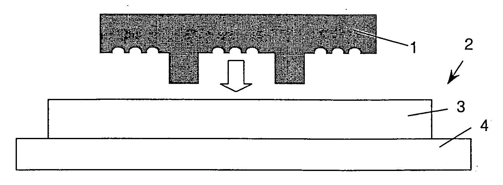
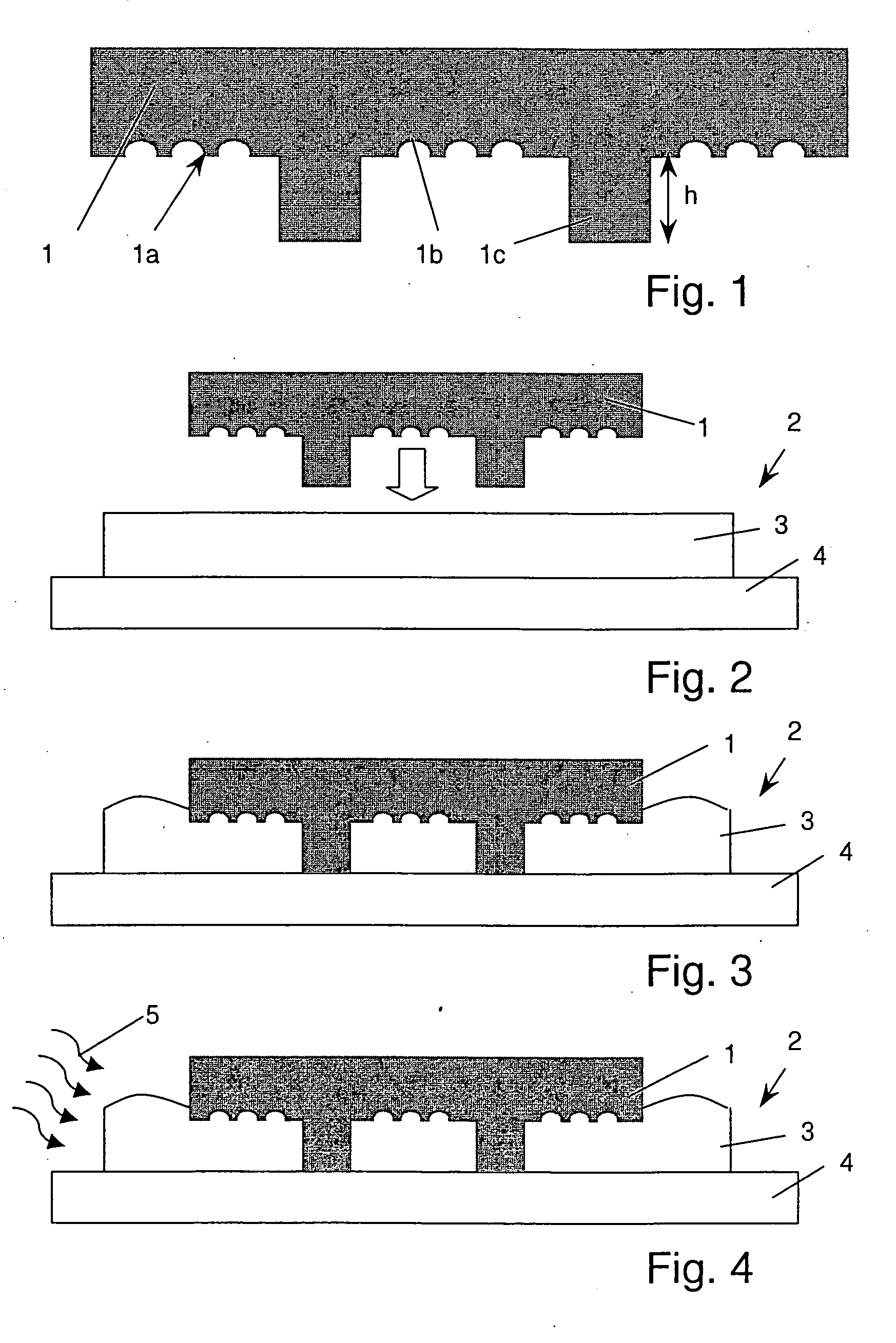
[0034] The replication tool 1 shown in FIG. 1 comprises a replication surface 1a with negative structural features being a negative of structural features to be shaped on a surface of a micro-optical element. More concretely, the embodiment shown very schematically in the figures has indentations 1b corresponding to protrusions of a surface of a micro-optical element. Typical dimensions (characteristic depths / heights and often also widths) of the structural features are a few micrometers, for example 0.5 μm-200 μm, preferably between 1 μm and about 50 μm or between 1 μm and about 30 μm. The replication tool further has spacers 1c protruding from the replication surface. The height h of the spacers is for example between 2 μm and 1000 μm, preferably between 2 μm and 200 μm, for example between 10 μm and 40 μm, and it usually is such that the spacers protrude further than the highest negative structural features. The geometrical dimension (shape, height, diameter) and the distribution...


PUM

PropertyMeasurementUnit
Elastomericaaaaaaaaaa
Viscosityaaaaaaaaaa
Areaaaaaaaaaaa

Abstract

According to the invention, a micro-structured element is manufactured by replicating/shaping (molding or embossing or the like) a 3D-structure in a preliminary product using an replication tool (1). The replication tool comprises a spacer portion (1c) protruding from a replication surface (1a). The replica (the micro-structured element, for example the micro-optical element or micro-optical element component) may be made of epoxy, which is cured—for example UV cured—while the replication tool is still in place. The replication process may be an embossing process, where the deformable or viscous or liquid component of the preliminary product to be shaped is placed on a surface and then the replication tool is pressed against this surface. As an alternative, the replication process may be a molding process.

Description

BACKGROUND OF THE INVENTION [0001] 1. Field of the Invention [0002] The invention is in the field of manufacturing micro-structured elements such as micro-optical elements or micro-optical systems. It also extends to Micro-Electro-Mechanical Systems (MEMS) and combined micro-optical and electronic and / or mechanical systems such as Micro-Opto-Electro-Mechanical Systems (MOEMS). More concretely, it deals with a method of replicating—for example by an embossing or molding process—an element into a micro-structured element, with a replication tool, and with a method of manufacturing a replication tool. [0003] 2. Description of the Related Art [0004] Micro-optical elements have gained increasing importance. Micro-optical elements here are elements of any kind that rely on micro-optics. The term ‘micro-optical elements’ here includes systems comprising electronic and / or mechanical components, such as, for example, the MOEMS. Micro-optics, as opposed to conventional optics, is based on fin...

Claims


Application Information

Patent Timeline
IPC IPC(8): B29C33/40B29C33/00B29C43/02B29D11/00B81C99/00G02B5/18
CPCB29C43/021B29D11/00B29L2011/0016G02B5/1852B29L2011/00B29D11/00326B29C2059/023B29C59/022Y10T29/49B29D11/0048B29D11/00365
Inventor RUDMANN, HARTMUTMACIOSSEK, ANDREASROSSI, MARKUS
Owner AMS SENSORS SINGAPORE PTE LTD
Why Eureka
Try Eureka