Liquid crystal display apparatus

Inactive Publication Date: 2006-06-01
SANYO ELECTRIC CO LTD +1
View PDF8 Cites 13 Cited by
  • Summary
  • Abstract
  • Description
  • Claims
  • Application Information

AI Technical Summary

Benefits of technology

[0044] Thanks to the features described above, the present invention offers the following benefits. According to the present invention, the electrically insulated black matrix is in an electrically floating state. Thus, when in contact with the metal support frame, the electrically insulated black matrix is at the same potential as the support frame; by contrast, when not in contact with the metal support frame, it is at an indefinite potential. In either case, the outer electrically insulated black matrix is electrically separated from the inner black matrix and the common electrode, and therefore no current flows between the metal support frame and the other black matrix. Thus, no short circuiting or electrolytic corrosion occurs through the electrically insulated black matrix. Moreover, no light leaks even when viewed from an oblique direction, and this helps enhance display quality at the periphery.
[0045] According to the present invention, the electrically insulated black matrix is laid equidistantly from an end of one of the substrates. Thus, the distance between the metal support frame and the electrically insulated black matrix is constant, regardless of where it is measured. This eliminates variations in the quality of the liquid crystal display apparatus.
[0046] According to the present invention, the electrically insulated black matrix is composed of a plurality of black matrices, each electrically separated from another. Thus, when the plurality of black matrices are separated parallel to the direction of their length, the electrical resistance between the metal support frame and the other black

Problems solved by technology

Planer-light-source backlights can be made slim, but are expensive, making them a less favored choice.
Here, when the motherboards are cut, a slight error may arise in the cutting positions, causing an elect

Method used


Image

  • Liquid crystal display apparatus
  • Liquid crystal display apparatus
  • Liquid crystal display apparatus

Examples


Embodiment Construction

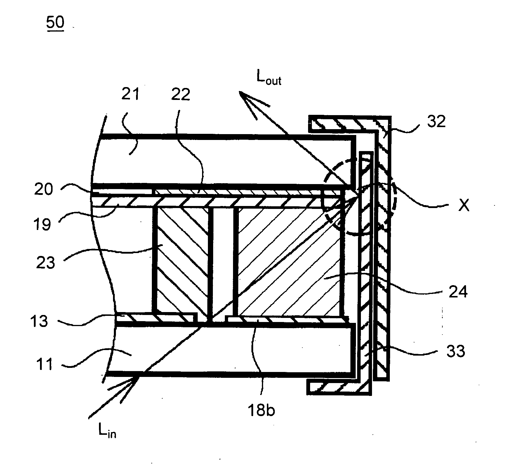
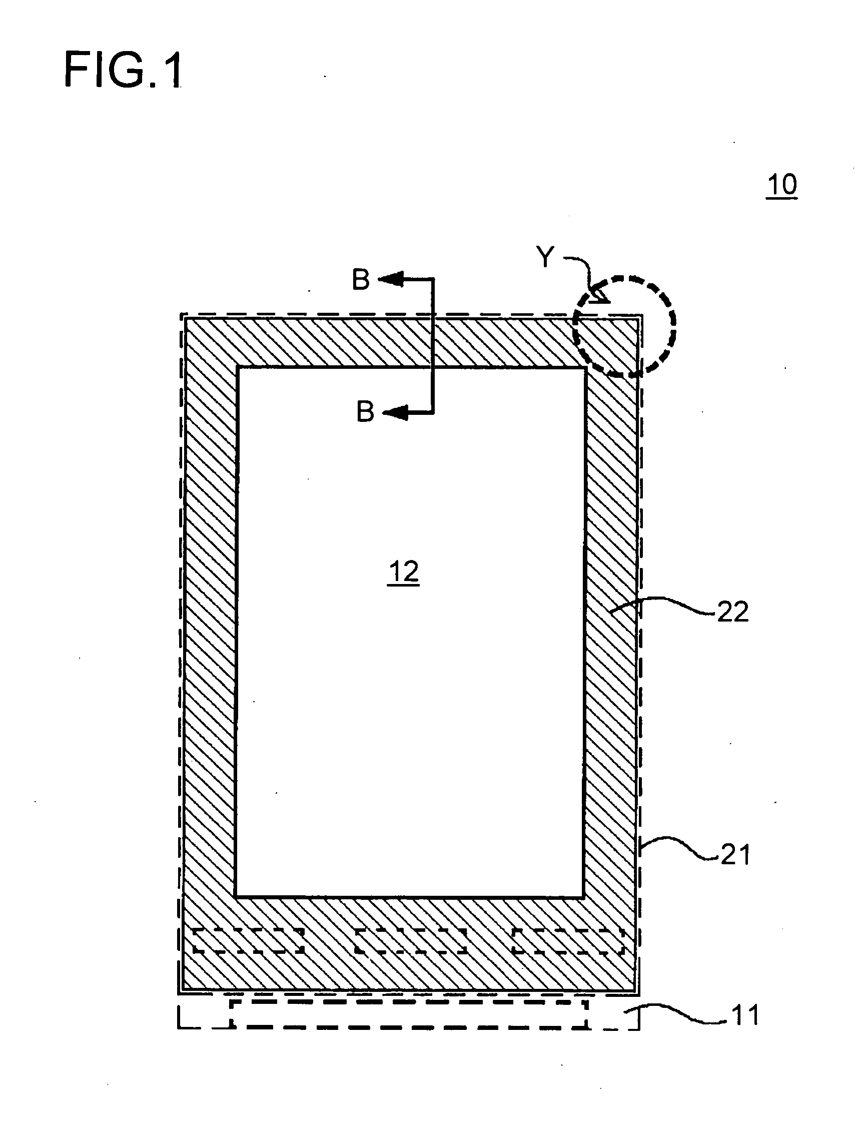
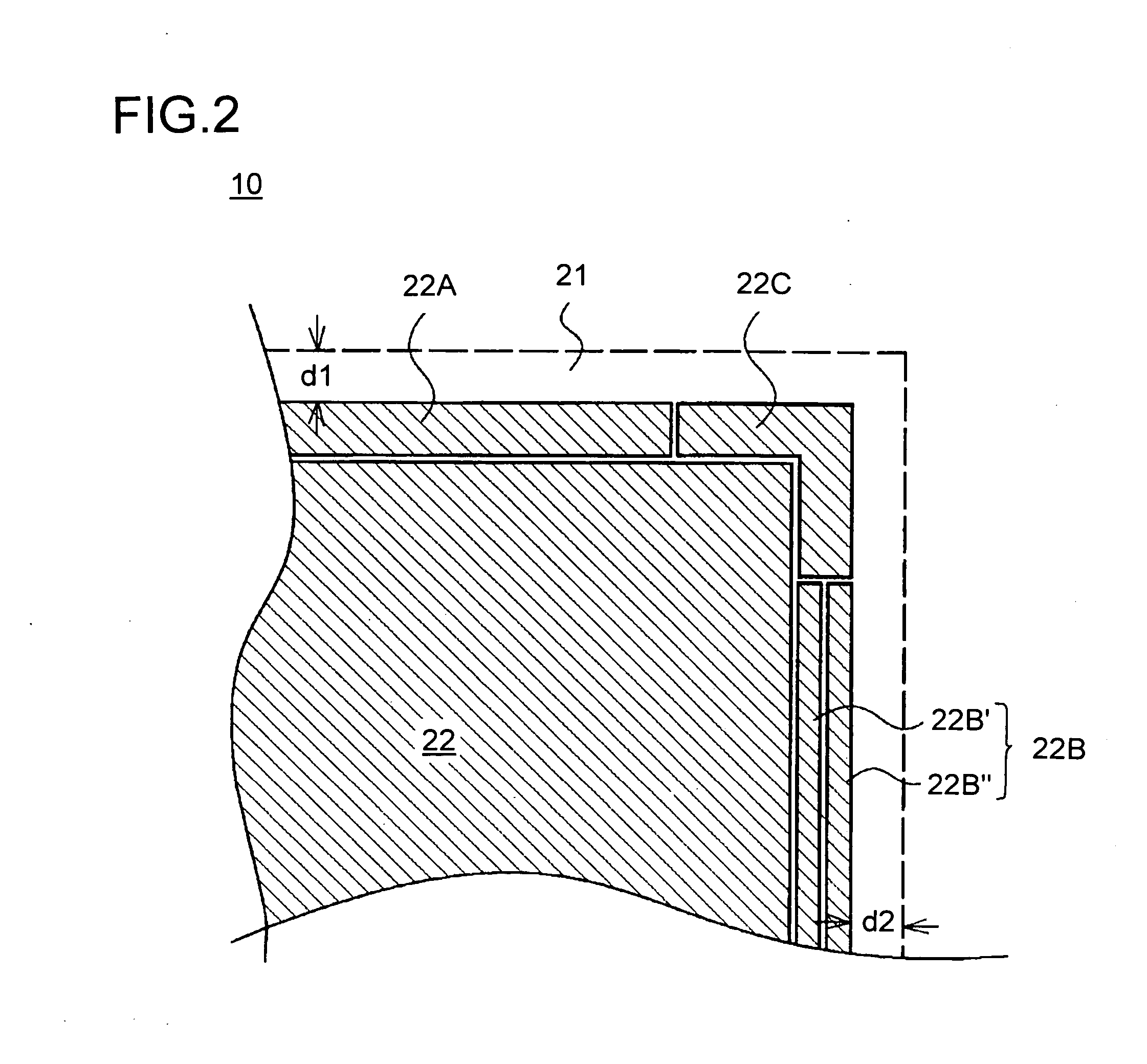
[0057] Hereinafter, the best mode in which the present invention can be carried out will be described with reference to the drawings, taking up a transmissive liquid crystal display apparatus as an example. FIG. 1 is a plan view showing the liquid crystal display panel used in a liquid crystal display apparatus embodying the invention. FIG. 2 is an enlarged view of part Y shown in FIG. 1. FIG. 3 is a section of FIG. 1 taken along line B-B, showing the liquid crystal display panel shown in FIG. 1 held between support frames. In FIG. 1, part of the second substrate, which forms the display surface, is cut out to show the interior. For the sake of convenience, such parts similar to those found in the conventional example shown in FIGS. 4 to 8 are identified with common reference numerals, and no explanations thereof will be repeated.

[0058] The liquid crystal display panel 10 has a first and a second substrate 11 and 21, both transparent, disposed to face each other. On the surface of ...


PUM


Abstract

In a liquid crystal display apparatus having a backlight disposed behind a liquid crystal display panel 10, the liquid crystal display panel 10 has first and second substrates 11 and 21 disposed to face each other. The second substrate 21 has a common electrode 20 laid in a display area 12 thereon. The second substrate 21 further has a light-shielding inner black matrix 22 laid around the display area 12 and a light-shielding electrically insulated black matrix 22A, 22B, and 22C laid outside the inner black matrix 22 and electrically separated from the inner black matrix 22 and the common electrode 19. The liquid crystal display panel 10 is held, at the periphery thereof, by metal support frames 32 and 33.

Description

[0001] This application is based on Japanese Patent Application No. 2004-286356 filed on Sep. 30, 2004, the contents of which are hereby incorporated by reference. BACKGROUND OF THE INVENTION [0002] 1. Field of the Invention [0003] The present invention relates to a liquid crystal display apparatus, and more particularly to a liquid crystal display apparatus having a light-shielding black matrix (BM) disposed around a peripheral portion of a liquid crystal display panel. [0004] 2. Description of Related Art [0005] In a liquid crystal display panel, two transparent substrates having electrodes and the like formed thereon are placed to face each other, and are fixed together with a sealing member laid around the periphery thereof. The transparent substrates and the sealing member thus leave a space inside it, where liquid crystal is sealed in. For example, an active-matrix liquid crystal display panel is structured as follows. On one substrate, signal lines and scan lines are laid in ...

Claims


Application Information

Patent Timeline
IPC IPC(8): G02F1/1333
CPCG02F1/133308G02F1/133512G02F1/133608G02F1/133615G02F1/1335G02F1/1345
Inventor ARAMATSU, YOSHIAKIKOBAYASHI, OSAMU
Owner SANYO ELECTRIC CO LTD
Why Eureka
Try Eureka