Tri-state servowriter driver with slow return to zero

Inactive Publication Date: 2006-06-01
IBM CORP
View PDF19 Cites 12 Cited by
  • Summary
  • Abstract
  • Description
  • Claims
  • Application Information

AI Technical Summary

Benefits of technology

[0008] As stated above, while writing the magnetic pattern, the magnetic head is adapted to change the polarity of output more abruptly than when the driver gradually changes the output from the magnetic head before and after a rest state. By gradually changing the output from the magnetic head before and after a rest state, the driver produces uniform signal pulses upon playback of the magnetic pattern and avoids half amplitude pulses at the beginning and ends of playback of the magnetic pattern. When the driver gradually changes the output of the magnetic head before and after a rest state, the transition time between the beginning or the ending of a rest state and a charged output is preferably at least five times longer than the transition time during the write sequence when the magnetic head is alternating between positive and negative write states and passes a point at which no current is output. Additionally, when the driver gradually changes the output of the magnetic head before and after a rest state, the transition time between one of the write states and the rest state is no greater than the time, during a write sequence, that transpires between the writing of centerlines of two consecutive servo bands in the magnetic pattern less the time it takes to write a single servo band in the magnetic pattern. The method also includes performing a gap recording process by using first and second angled write elements on the magnetic head to write the magnetic pattern on the storage media. The resulting magnetic pattern includes a first pattern section and a second pattern section longitudinally offset and symmetrical relative to each other. Lastly, the method includes the step of maintaining the magnetic head in a rest state, when the portion of the storage media containing the second write element passes the first angled write portion, to avoid overwriting.

Problems solved by technology

Weak read-back signals from the servo bands can decrease the accuracy of lateral position of magnetic heads.

Method used


Image

  • Tri-state servowriter driver with slow return to zero
  • Tri-state servowriter driver with slow return to zero
  • Tri-state servowriter driver with slow return to zero

Examples


Embodiment Construction

[0019] The present invention and the various features and advantageous details thereof are explained more fully with reference to the non-limiting embodiments that are illustrated in the accompanying drawings and detailed in the following description. It should be noted that the features illustrated in the drawings are not necessarily drawn to scale. Descriptions of well-known components and processing techniques are omitted so as to not unnecessarily obscure the present invention. The examples used herein are intended merely to facilitate an understanding of ways in which the invention may be practiced and to further enable those of skill in the art to practice the invention. Accordingly, the examples should not be construed as limiting the scope of the invention.

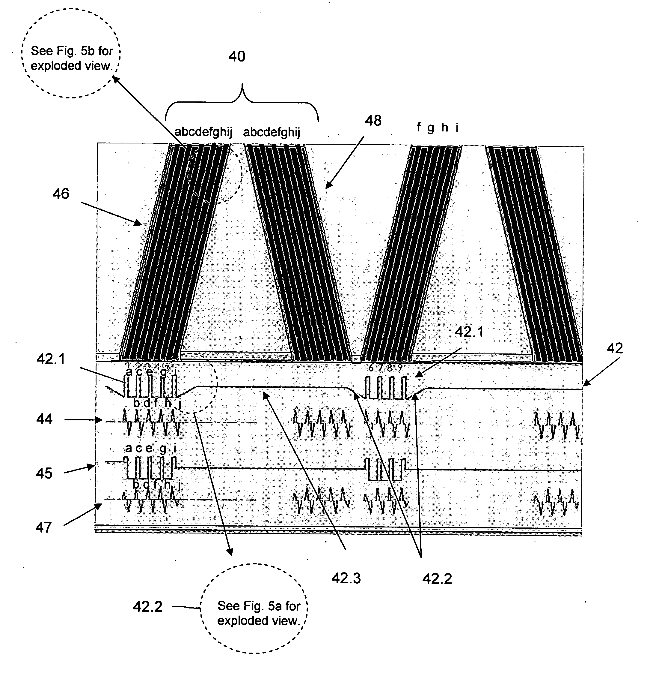
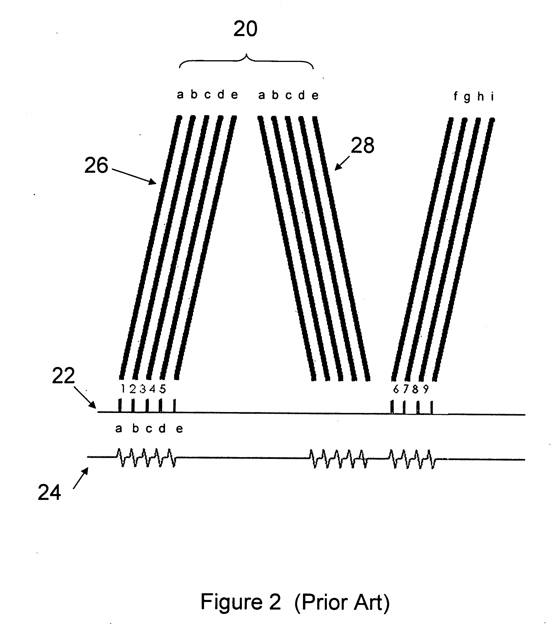
[0020] As stated above, prior art servo bands are prewritten onto the tapes by magnetic heads controlled by uni-polar drivers, such that the spaces between bands have a zero charge. Using a uni-polar driver produces weak ...


PUM


Abstract

A method and apparatus for writing timing-based magnetic servo band patterns on magnetic storage media. The apparatus includes a magnetic head and a tri-state driver. The driver is adapted to control three magnetic head states including two writes states having positive and negative current outputs, respectively, for performing a write sequence and a rest state, having no current output for avoiding overwriting of the magnetic pattern between write sequences. The driver is further adapted to gradually change the magnetic head state from a rest state to a write state before beginning a write sequence and to gradually change the magnetic head state back to a rest state upon completing a write sequence. Thus, strong uniform signal pulses are produced upon playback of the magnetic pattern.

Description

BACKGROUND OF THE INVENTION [0001] 1. Field of the Invention [0002] This invention relates to magnetic storage media and more specifically to an apparatus and method for writing timing-based servo patterns on magnetic storage media. [0003] 2. Description of the Related Art [0004] Magnetic storage media such as linear tape storage systems are commonly used for storing large amounts of digital data. The data is formatted by magnetic heads on linear tapes in a plurality of tracks that extend longitudinally along the tape. Servo band patterns on the tapes are read by the magnetic heads when reading from or writing onto the tape in order to ensure accurate lateral positioning of the magnetic heads relative to the tape. These servo bands are prewritten onto the tapes by magnetic heads controlled by uni-polar drivers (positive or negative), such that transitions between bands have zero current. U.S. Pat. No. 6,169,640 issued to Fasen on Jan. 2, 2001 for “Servo Band Identification in Linear...

Claims


Application Information

Patent Timeline
IPC IPC(8): G11B21/02G11B5/09G11B5/584
CPCG11B5/584
Inventor EATON, JAMES HOWARDEATON, GLYNDA WILLIAMS
Owner IBM CORP
Why Eureka
Try Eureka