Exchange biased magnetic head having confined current path

Inactive Publication Date: 2006-06-01
TDK CORPARATION +1
View PDF31 Cites 4 Cited by
  • Summary
  • Abstract
  • Description
  • Claims
  • Application Information

AI Technical Summary

Problems solved by technology

However, as a result of the thin free layer, there is a related art problem of a stronger spin transfer effect.
As a result, the related art spin transfer effect problem is increased.

Method used


Image

  • Exchange biased magnetic head having confined current path
  • Exchange biased magnetic head having confined current path
  • Exchange biased magnetic head having confined current path

Examples


Embodiment Construction

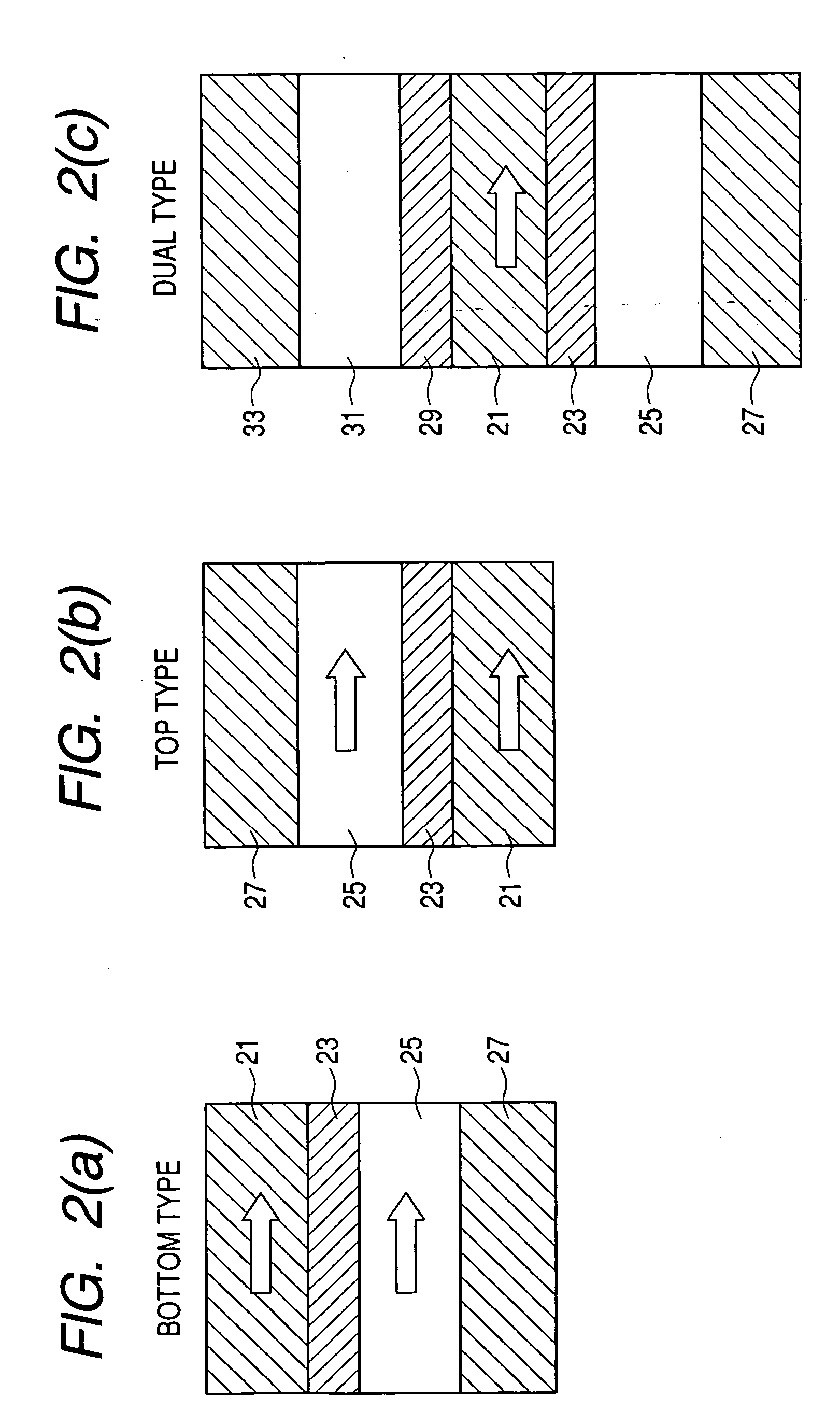
[0044] The present invention includes an in-stack biased (also referred to as “exchange biased”) magnetic head having a confined current path according to the exemplary, non-limiting embodiments described herein, and equivalents thereof as would be known by one of ordinary skill in the art.

[0045] In the present invention, the term “read head” is used interchangeably with the term “magnetic sensor”, and refers to the overall apparatus for sensing data from a recording media. In this regard, “magnetic sensor” is one particular type of “magnetic element”, and where magnetic sensors are used in the specification, other magnetic elements (e.g., random access memory or the like) may be substituted therein, as would be known by one of ordinary skill in the art.

[0046] Additionally, the term “magnetic element” is defined to include “magnetoresistance effect element” and / or “magnetoresistance element” as is understand by those of ordinary skill in this technical field. However, the present ...


PUM


Abstract

An in-stack bias is provided for stabilizing the free layer of a ballistic magneto resistive (BMR) sensor. In-stack bias includes a decoupling layer that is a spacer between the free layer and a ferromagnetic stabilizer layer of the in-stack bias, and an anti-ferromagnetic layer positioned above the ferromagnetic layer. The spacer is a nano-contact layer having magnetic particles positioned in a non-magnetic matrix. The free layer may be single layer, composed or synthetic, and the in-stack bias may be laterally bounded by the sidewalls, or alternatively, extend above the sidewalls and spacer. Additionally, a hard bias may also be provided. The spacer of the in-stack bias results in the reduction of the exchange coupling between the free layer and ferromagnetic stabilizing layer, an improved AΔR due to confinement of current flow through a smaller area, and increased MR due to the domain wall created within the magnetic nano-contact.

Description

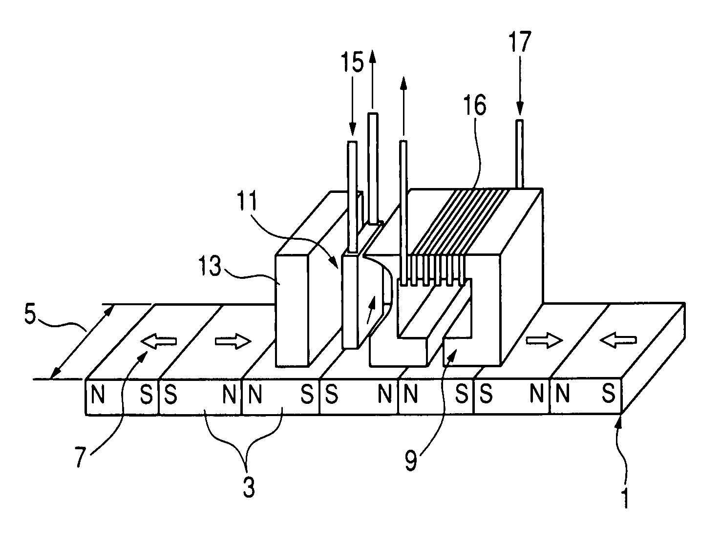
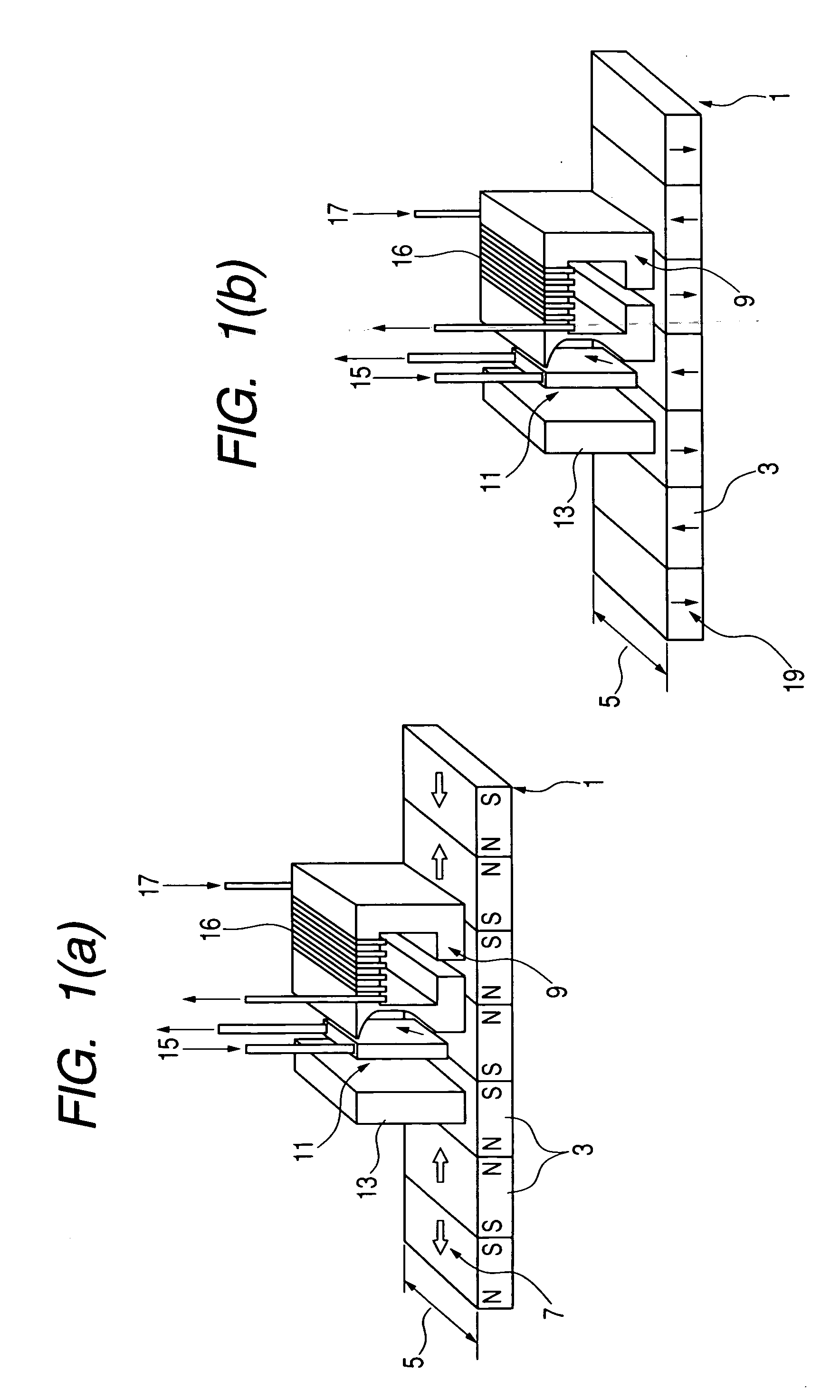
BACKGROUND OF THE INVENTION [0001] 1. Technical Field [0002] The present invention relates to a magnetic head having a confined current path, and more specifically, to a ballistic magneto resistive (BMR) sensor having a free layer stabilized by an in-stack bias and spacer-decoupling layer including nanoparticles. [0003] 2. Related Art [0004] In the related art magnetic recording technology such as hard disk drives, a head is equipped with a reader and a writer that operate independently of one another. FIGS. 1 (a) and (b) illustrate related art magnetic recording schemes. A recording medium 1 having a plurality of bits 3 and a track width 5 has a magnetization 7 parallel to the plane of the recording media. As a result, a magnetic flux is generated at the boundaries between the bits 3. This is commonly referred to as “longitudinal magnetic recording”. [0005] Information is written to the recording medium 1 by an inductive write element 9, and data is read from the recording medium 1...

Claims


Application Information

Patent Timeline
IPC IPC(8): G11B5/127G11B5/33
CPCB82Y10/00B82Y25/00G11B5/1278G11B5/3909G11B5/3932G11B2005/0018G11B2005/0029G11B2005/3996H01L43/08H10N50/10
Inventor SBIAA, RACHIDSATO, ISAMUMORITA, HARUYUKI
Owner TDK CORPARATION
Why Eureka
Try Eureka