Image processing device and image processing program

a technology of image processing and image processing program, which is applied in the field of image processing apparatus, can solve the problems of inability to obtain transmittance data of a completely uniform surface with an electronic camera, the video camera in the related art is not designed to handle changes in optical conditions other than aperture values, and the dust conditions that change over time appearing in photographed images tend to be more serious. , to achieve the effect of removing the mismatch of optical conditions

Active Publication Date: 2006-06-01
NIKON CORP
View PDF24 Cites 57 Cited by
  • Summary
  • Abstract
  • Description
  • Claims
  • Application Information

AI Technical Summary

Benefits of technology

[0011] In the area of copiers and scanners, dust data are obtained prior to or concurrently with the main scan, to be used to eliminate the adverse effect of dust that changes over time. Since a copier or a scanner, unlike a camera, includes an illuminating means that uniformly illuminates the surface of an original copy or the film surface set at a fixed distance, transmittance data can be obtained relatively easily by adding a completely uniform reflecting surface or by further providing an infrared illuminating means. However, except for during the inspection conducted in the manufacturing process, transmittance data of a completely uniform surface cannot be obtained readily with an electronic camera.
[0013] The present invention provides an image processing apparatus and an image processing program, with which the adverse effect of dust or the like can be eliminated in a desirable manner from image data obtained by photographing an image with an electronic camera or the like.
[0053] According to the 40th aspect of the invention, in the image processing apparatus according to any of the 37th through 39th aspects, it is preferred that: the defect information generating unit includes an optical condition conversion unit that converts at least either the first image or the second image so as to conform to a specific optical condition, in order to eliminate a mismatch of the optical conditions for the first image and the second image.
[0061] According to the 48th aspect of the invention, in the image processing apparatus according to the 47th aspect, it is preferred that: the defect information generating unit includes an optical condition conversion unit that converts at least either the first image or the second image so as to conform to a specific optical condition, in order to eliminate a mismatch of the optical conditions for the first image and the second image.

Problems solved by technology

However, the anti-dust measures adopted in cameras in the related art only target fixed dust having become adhered to optical components during the manufacturing process and do not deal with dust, the conditions of which may change over time depending upon the frequency of use.
The problem of dust conditions that change over time appearing in photographed images tends to be more serious in single lens reflex cameras that allow the use of exchangeable lenses, which are gaining popularity today, since the optical components disposed to the front of the image sensor are uncovered.
However, except for during the inspection conducted in the manufacturing process, transmittance data of a completely uniform surface cannot be obtained readily with an electronic camera.
Video cameras in the related art are not designed to handle changes in the optical conditions other than the aperture value.

Method used


Image

  • Image processing device and image processing program
  • Image processing device and image processing program
  • Image processing device and image processing program

Examples


first embodiment

[0113] (Structures of Electronic Camera and Personal Computer)

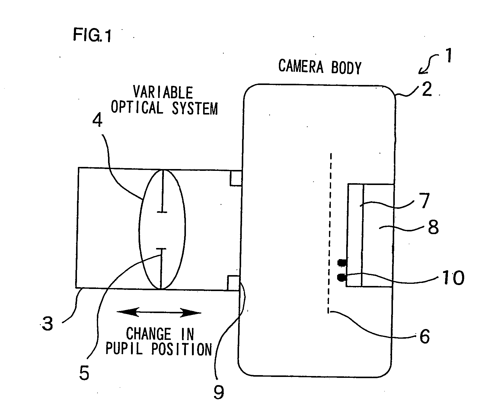
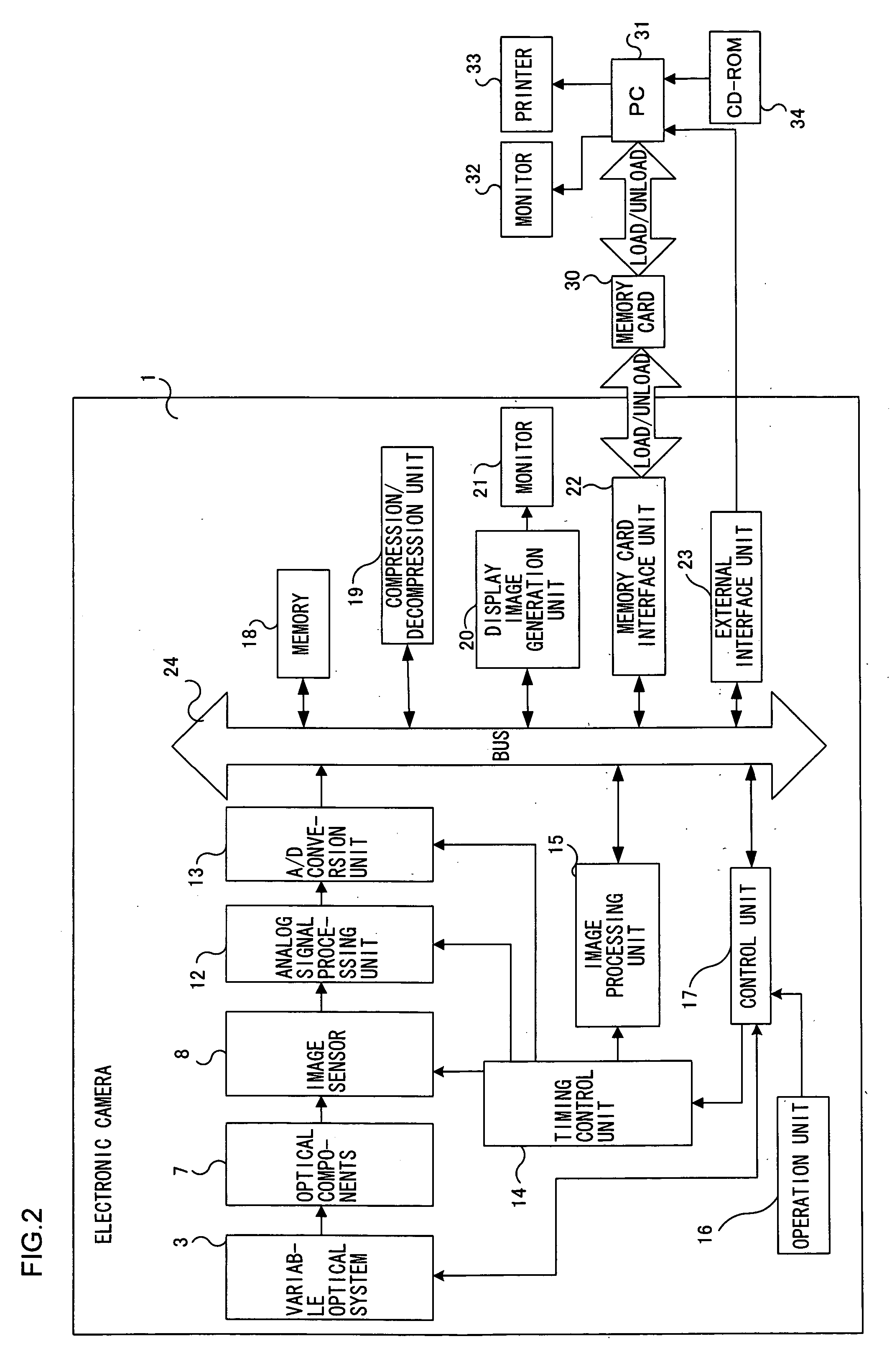
[0114]FIG. 1 shows the structure of a single lens reflex electronic still camera (hereafter referred to as an electronic camera) that allows the use of exchangeable lenses. The electronic camera 1 includes a camera body 2 and a variable optical system 3 constituted with a mount-type exchangeable lens. The variable optical system 3 includes a built-in lens 4 and a built-in aperture 5. While the lens 4 is constituted with a set of a plurality of optical lenses, a single representative lens is shown in the figure, and the position of the lens 4 is referred to as a main pupil position (hereafter simply referred to as a pupil position). The variable optical system 3 may be a zoom lens. The pupil position is indicated with a value determined in correspondence to the lens type or the zoom position of the zoom lens. It may be affected by the focal length, as well.

[0115] The camera body 2 includes a shutter 6, optical components...

second embodiment

[0156] In the second embodiment, a single reference image photographed to obtain dust information is used for dust shadow removal in conjunction with a plurality of images photographed under varying optical photographing conditions. Since the structures of the electronic camera 1 and the PC 31 functioning as the image processing apparatus are identical to those in the first embodiment, their explanation is omitted.

[0157] (Operation Executed on Electronic Camera Side)

[0158]FIG. 7 shows the photographing procedure executed at the electronic camera 1 in the second embodiment.

1) A uniform surface photographing operation 201 is executed at a pupil position P0 and an aperture value A0 and reference image data 0 are output.

2) A regular photographing operation 202 is executed at a pupil position P1 and an aperture value A1 and correction target image data 1 are output.

3) A regular photographing operation 203 is executed at a pupil position P2 and an aperture value A2 and correction ...

third embodiment

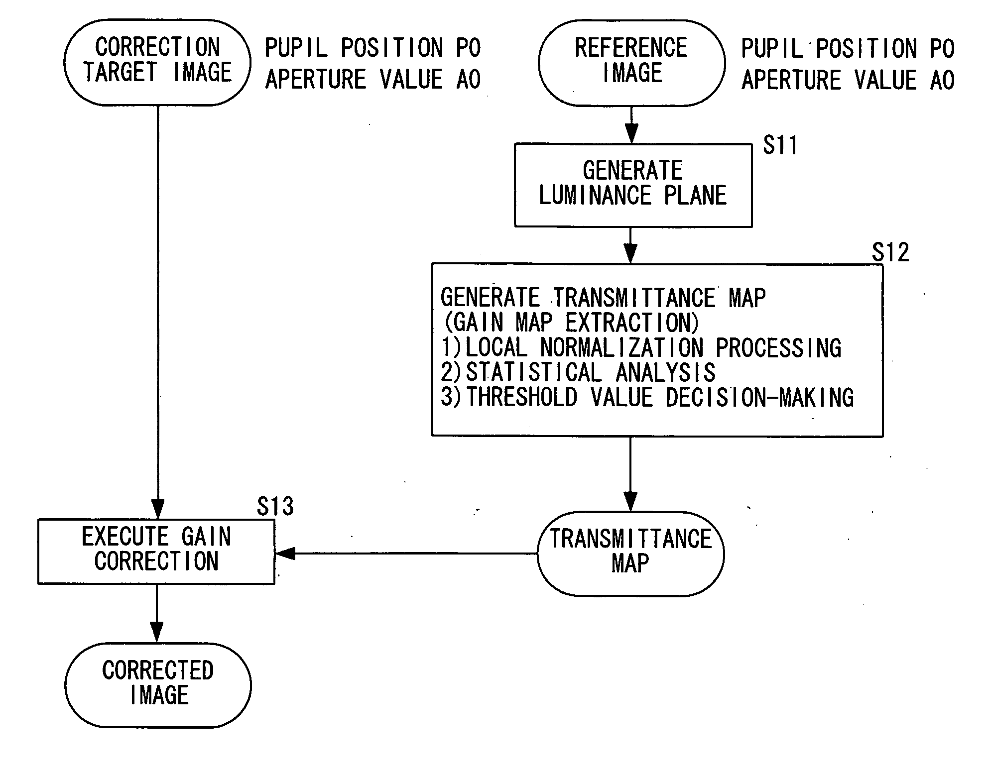
[0179] In the third embodiment, dust shadows in the correction target image are detected and eliminated without using any uniform surface reference image. The method adopts a basic principle that once a flat area (local image area over which the image is uniform) is found in the correction target image, the dust transmittance map generation processing (gain map extraction) executed on the reference image in the first embodiment can also be executed in conjunction with the correction target image. Since the electronic camera 1 and the PC 31 functioning as the image processing apparatus adopt structures similar to those in the first embodiment, their explanation is omitted.

[0180] (Operation Executed on Electronic Camera Side)

[0181]FIG. 14 shows the photographing procedure executed at the electronic camera 1 in the third embodiment.

1) A regular photographing operation 301 is executed at a pupil position P1 and an aperture value A1 and correction target image data 1 are output.

2) ...


PUM


Abstract

An image processing apparatus includes: an image obtaining unit that obtains an image captured with an image sensor; and a defect information generating unit that generates defect information indicating a defect within the image having been obtained, based upon a value at a target pixel and an average value of a plurality of pixel values corresponding to pixels present within a predetermined range containing the target pixel.

Description

[0001] The disclosures of the following priority applications are herein incorporated by reference: [0002] Japanese Patent Application No. 2002-379719 filed Dec. 27, 2002 [0003] Japanese Patent Application No. 2002-379720 filed Dec. 27, 2002 [0004] Japanese Patent Application No. 2002-379721 filed Dec. 27, 2002 [0005] Japanese Patent Application No. 2003-307355 filed Aug. 29, 2003 [0006] Japanese Patent Application No. 2003-307356 filed Aug. 29, 2003 [0007] Japanese Patent Application No. 2003-307357 filed Aug. 29, 2003 TECHNICAL FIELD [0008] The present invention relates to an image processing apparatus that eliminates the adverse effect of dust and the like in image data obtained by photographing an image with an electronic camera or the like. BACKGROUND ART [0009] A technology in the related art whereby a white pattern is photographed at each aperture value and correction information is recorded in advance to be used to correct the adverse effect of dust that has entered the opti...

Claims


Application Information

Patent Timeline
Patent Type & Authority Applications(United States)
IPC IPC(8): G06K9/40H04N5/367
CPCH04N1/4097H04N5/3675H04N25/683
Inventor ISHIGA, KENICHI
Owner NIKON CORP
Why Eureka
Try Eureka