Bridge construction system and method

a construction system and bridge technology, applied in bridge construction, bridge materials, construction, etc., can solve the problems of system time, limited access to work site, so as to achieve cost efficiency and facilitate construction.

Inactive Publication Date: 2006-06-08
RAPID PRECAST CONSTR SYST
View PDF11 Cites 31 Cited by
  • Summary
  • Abstract
  • Description
  • Claims
  • Application Information

AI Technical Summary

Benefits of technology

[0003] The majority of bridges constructed in the United States use concrete as the primary construction material and the use of pre-stressing has expanded the span capability of concrete bridges. The predominant method of deck or roadway construction on concrete bridges is full depth cast-in-place deck slabs. Another method is a full depth prefabricated deck system and a third is a combination of a partial depth pre-cast deck slab and a cast-in-place deck.
[0007] Another alternative to full depth cast-in-place deck slabs is partial depth pre-cast pre-stressed deck slabs and a cast-in-place deck topping. These slabs are normally produced in relatively narrow widths and placed across the bridge girders in sequence. The smaller overall size allows these slabs to be transported directly to the site over the completed bridge roadway. This system provides the advantages of offsite prefabrication and overcomes the road surface smoothness problem inherent in full depth pre-cast deck slabs. In this system the partial depth pre-cast pre-stressed deck slabs serve as a form for a cast in place deck topping. However, because of variances in the elevation of the supporting bridge girders, and lack of continuity in the partial depth pre-cast pre-stressed deck slabs, the cast-in-place deck topping can develop “reflective” cracking outlining the pre-cast pre-stressed deck slabs below the deck topping.
[0011] Accordingly, it is an object of this invention to provide a bridge construction system and method which is more cost efficient and easier to construct.

Problems solved by technology

In addition to the problems inherent in water based bridge sites, access to the work site may also be limited in confined urban areas because of existing construction and right-of-way restrictions.
Besides being labor intensive, this system requires access from under the bridge structure.
Since, by the very nature of a bridge, land access is usually not available; any work done under a bridge deck requires extensive scaffolding.
Perhaps the most serious drawback to this system is the time involved.
This system is particularly unsuitable for continuous span bridge structures with limited or no access other than the bridge itself.
One disadvantage to this system is misalignment between adjacent panels due to variances in the elevation of the supporting bridge girders which makes it difficult to maintain a smooth road surface.
Another disadvantage is the crane capacity needed to place a full depth pre-cast deck slab.
If all construction materials and equipment must reach the construction site over the completed portion of a bridge, the weight of a full depth pre-cast deck slab needed to cover the next length of the bridge span along with the equipment needed to carry and place it may exceed the load capacity of the bridge.
Unfortunately, this gives rise to an increased number of joints on the road surface with resultant problems in maintaining road smoothness.
However, because of variances in the elevation of the supporting bridge girders, and lack of continuity in the partial depth pre-cast pre-stressed deck slabs, the cast-in-place deck topping can develop “reflective” cracking outlining the pre-cast pre-stressed deck slabs below the deck topping.
Whether full depth or partial depth pre-cast pre-stressed deck slabs are used, problems in the deck or road surface depend to a great extent on the alignment of the deck slabs one to the next and the foundation upon which they rest.
Part of the difficulty arises because of the way pre-stressed concrete bridge girders are made.
The girder will deflect when placed under load but there may be differences in deflection between adjacent girders.
This has given rise to difficulties in alignment of deck slabs being installed on bridge girders with upward camber.

Method used


Image

  • Bridge construction system and method
  • Bridge construction system and method
  • Bridge construction system and method

Examples


Embodiment Construction

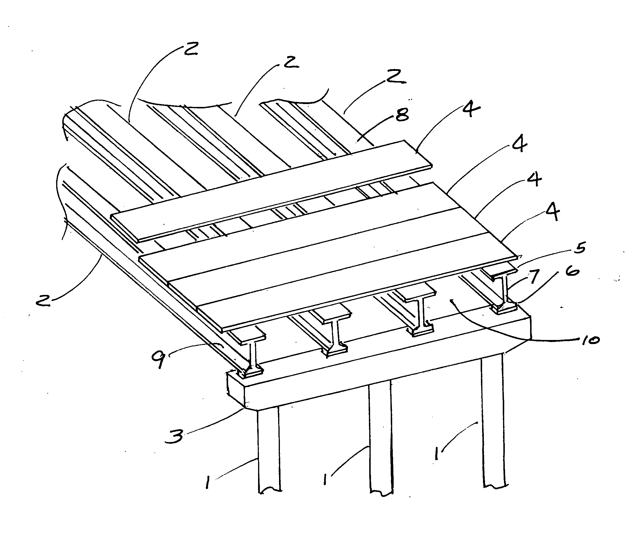
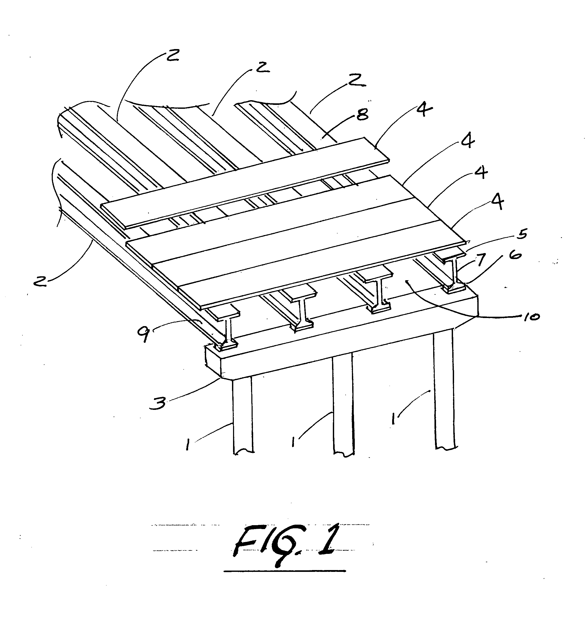
[0048] A typical concrete bridge construction is shown in FIG. 1, where the support pilings 1 are spaced in accordance with the designed span capability of the bridge girders 2 which are supported at the end of each span by a bent cap 3 resting on the support pilings 1. In the depicted embodiment the bridge girders 2 are pre-cast pre-stressed concrete. Although for many years the design of pre-cast pre-stressed concrete girders was based on compressive strengths of 5,000 to 6,000 psi, strengths up to 10,000 psi and above are now possible, giving rise to the term “high-performance concrete” (HPC). However, it is not intended that the present invention be limited to bridge construction using pre-cast pre-stressed concrete girders. A typical alternative would be a built-up steel plate girder.

[0049] As shown in FIG. 1, the bridge girders 2 have a typical cross section with an upper flange 5 and lower flange 6 connected by a vertical web 7. The upper flange 5 has an upper surface 8 whic...


PUM


Abstract

A system and method for construction of bridges and elevated roadways with pre-stressed concrete or steel bridge girders is provided including cast-in-place concrete deck slabs and partial and full depth pre-stressed pre-cast concrete deck slabs with post-tensioning conduits for post-tensioning a series of deck slabs. A plurality of bogies traveling on the lower flanges of the bridge girders are provided to place and level the deck slabs and to pre-load the bridge girders to eliminate camber before placement of the deck slabs on the bridge girders or to level, place, support and remove deck forms for a cast-in-place deck slab on the bridge girders. Also provided is a system for attachment of cast-in-place parapets.

Description

[0001] This application claims priority from U.S. Provisional application Ser. No. 60 / 633,525 (“the '525 application”) filed Dec. 6, 2004. The '525 application is incorporated herein by reference.[0002] This invention relates to a system and method for construction of bridges and elevated roadways with pre-cast pre-stressed concrete bridge girders or steel bridge girders and pre-cast pre-stressed concrete deck slabs or cast-in-place deck slabs, and, more particularly, to a system and method for placement of pre-cast pre-stressed concrete deck slabs on bridge girders with or without a cast-in-place deck topping or a forming system and method for cast-in-place deck slabs on bridge girders. [0003] The majority of bridges constructed in the United States use concrete as the primary construction material and the use of pre-stressing has expanded the span capability of concrete bridges. The predominant method of deck or roadway construction on concrete bridges is full depth cast-in-place ...

Claims


Application Information

Patent Timeline
Patent Type & Authority Applications(United States)
IPC IPC(8): E01D19/12
CPCE01D19/125E01D21/06E01D2101/28E01D2101/285
Inventor RONALD, HUGH D.THEOBALD, DON
Owner RAPID PRECAST CONSTR SYST
Why Eureka
Try Eureka