Infrared gas analyzer and infrared gas analysis method

a gas analyzer and infrared technology, applied in the direction of optical radiation measurement, instruments, measurement devices, etc., can solve the problems of not being able to fully get the advantage of the light source, and propose a configuration of an analyzer suitable for use, and achieve the effect of widening the dynamic range of the measurement range thereo

Inactive Publication Date: 2006-06-08
YOKOGAWA ELECTRIC CORP
View PDF11 Cites 2 Cited by
  • Summary
  • Abstract
  • Description
  • Claims
  • Application Information

AI Technical Summary

Benefits of technology

[0022] To achieve the above object, it is a first aspect of the invention to provide an infrared gas analyzer having a sample cell into which a sample gas is distributed, for detecting concentration of a measuring target component of the sample gas by taking advantage of variation in absorption amount of infrared rays having passed through the sample cell, wherein the infrared gas analyzer comprises a first infrared light source for irradiating the sample cell with infrared rays, a second infrared light source having a response characteristic equal to that of the first infrared light source, a detector for detecting a difference between the first infrared rays emitted from the first infrared light source, and having passed through the sample cell, and second infrared rays emitted from the second infrared light source, a light source drive controller for synchronously driving the first and second infrared light sources, respectively, and a measurement controller for providing the light source drive controller with instructions for respective drive amounts of the first and second infrared light sources while receiving an output signal from the detector, thereby generating a measurement output corresponding to the concentration of the measuring target component of the sample gas.
[0023] It is a second aspect of the invention to provide an infrared gas analysis method of detecting concentration of a measuring target component of a sample gas by taking advantage of variation in absorption amount of infrared rays having passed through a sample cell into which the sample gas is distributed, wherein the infrared gas analysis method comprises the steps of irradiating the sample cell with first infrared rays emitted from a first infrared light source, irradiating a balance side chamber with second infrared rays emitted from a second infrared light source having a response characteristic equal to that of the first infrared light source, synchronously driving the first and second infrared light sources while detecting a difference between the first infrared rays having passed through the sample cell, and the second infrared rays, and generating a measurement output corresponding to the concentration of the measuring target component of the sample gas.
[0024] Thus, with adoption of a configuration where the first infrared light source for irradiating the sample cell with the first infrared rays, and the second infrared light source having the response characteristic equal to that of the first infrared light source are provided, the first and second infrared light sources are synchronously driven while the difference between the first infrared rays having passed through the sample cell and the second infrared rays is detected, thereby generating the measurement output corresponding to the concentration of the measuring target component of the sample gas, the reference cell and the rotary sector are no longer required, so that it becomes possible implement the infrared gas analyzer of the simple configuration, capable of taking measurements with high precision when using the infrared light source excellent in thermal responsiveness, and capable of ON / OFF operations at high speed, and the infrared gas analysis method using the same.
[0025] Further, if the drive amount of the second infrared light source is controlled such that the output of the detector at the time of the measuring operation becomes always zero to thereby obtain the measurement output on the basis of the drive amount differential, this will enable the detector to be always used in a range where an output signal thereof remains small in value, thereby widening a dynamic range of a measurement range thereof.

Problems solved by technology

However, if the infrared light source described as above, is used for an analyzer of the conventional configuration as shown in FIG. 7, unnecessary constituent members are too many in view of the nature of the infrared light source, so that it is not possible to fully get the advantage of the light source.
Further, there have never been proposed a configuration of an analyzer suitable for use of the infrared light source described, and a measuring method using the same.

Method used


Image

  • Infrared gas analyzer and infrared gas analysis method
  • Infrared gas analyzer and infrared gas analysis method
  • Infrared gas analyzer and infrared gas analysis method

Examples


embodiment 1

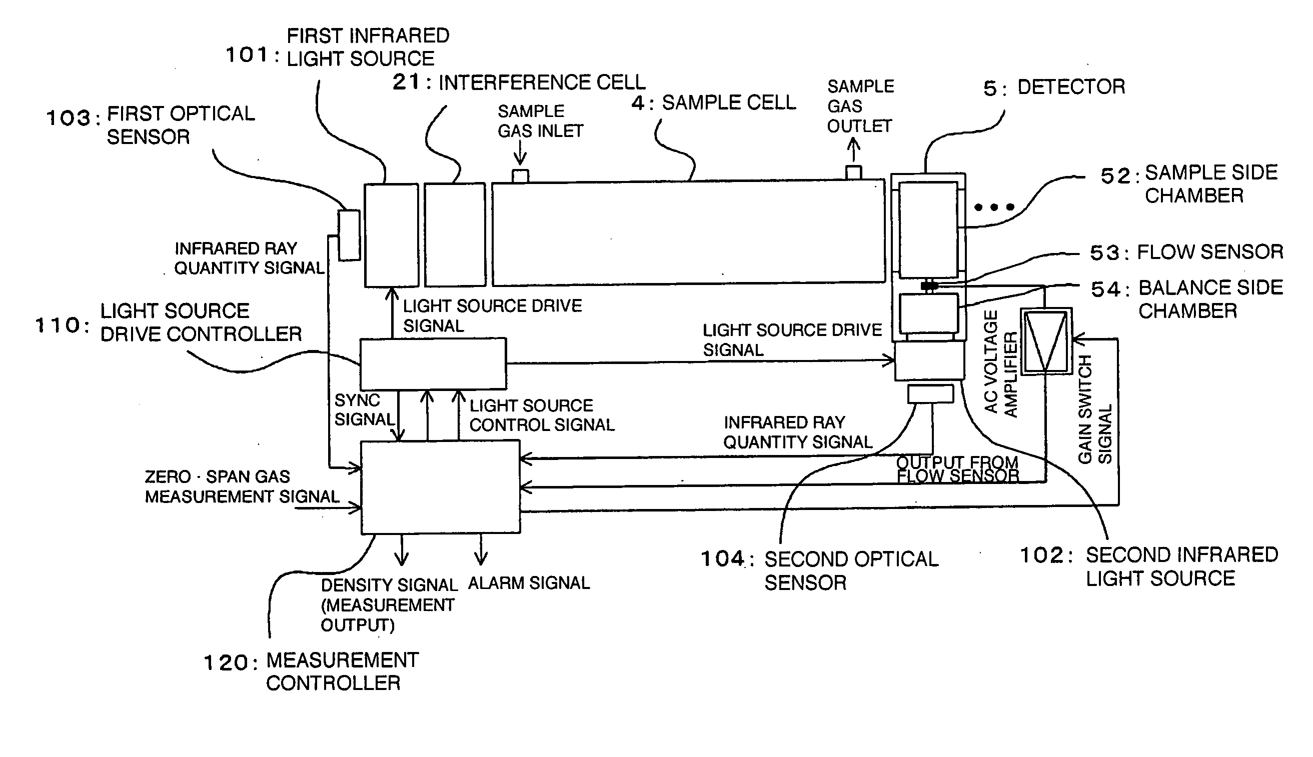
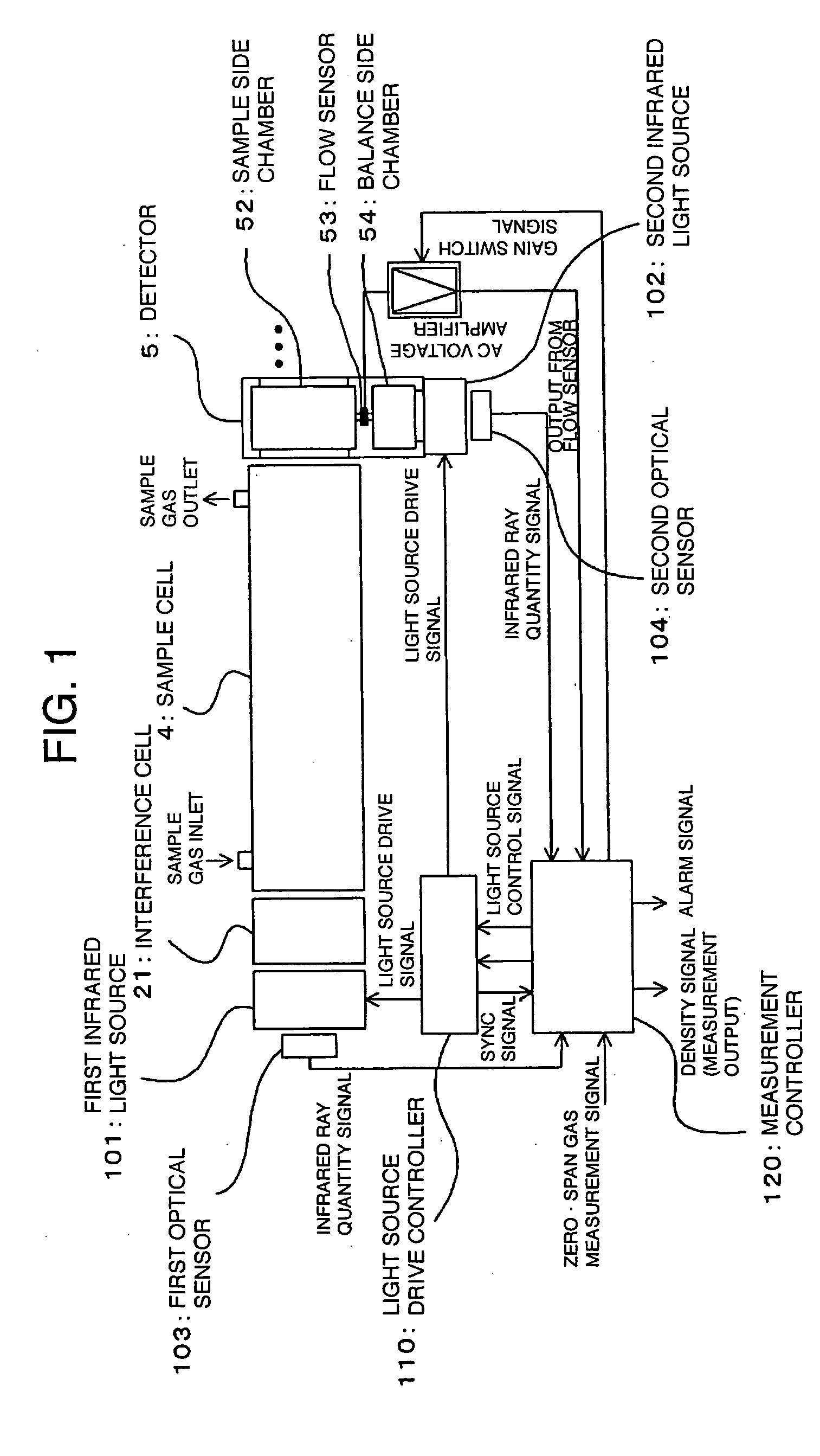
[0035]FIG. 1 is a block diagram showing one embodiment of an infrared gas analyzer, and an infrared gas analysis method using the same, according to the invention. In the figure, parts corresponding to those in FIG. 7 are denoted by like reference numerals. Reference numerals 101, 102 denote first and second infrared light sources, respectively, excellent in thermal responsiveness, such as one previously described with reference to FIG. 8, and the first infrared light source 101 irradiates a sample cell 4 with first infrared rays via an interference cell 21. Further, the second infrared light source 102 irradiates a balance side chamber 54 of a detector 5 with second infrared rays. In this case, the detector 5 has the balance side chamber 54 for receiving the second infrared rays, in place of the conventional reference side chamber 51, and a flow sensor 53 is provided in a gas distribution path linking a sample side chamber 52 for receiving the first infrared rays via the sample cel...

embodiment 2

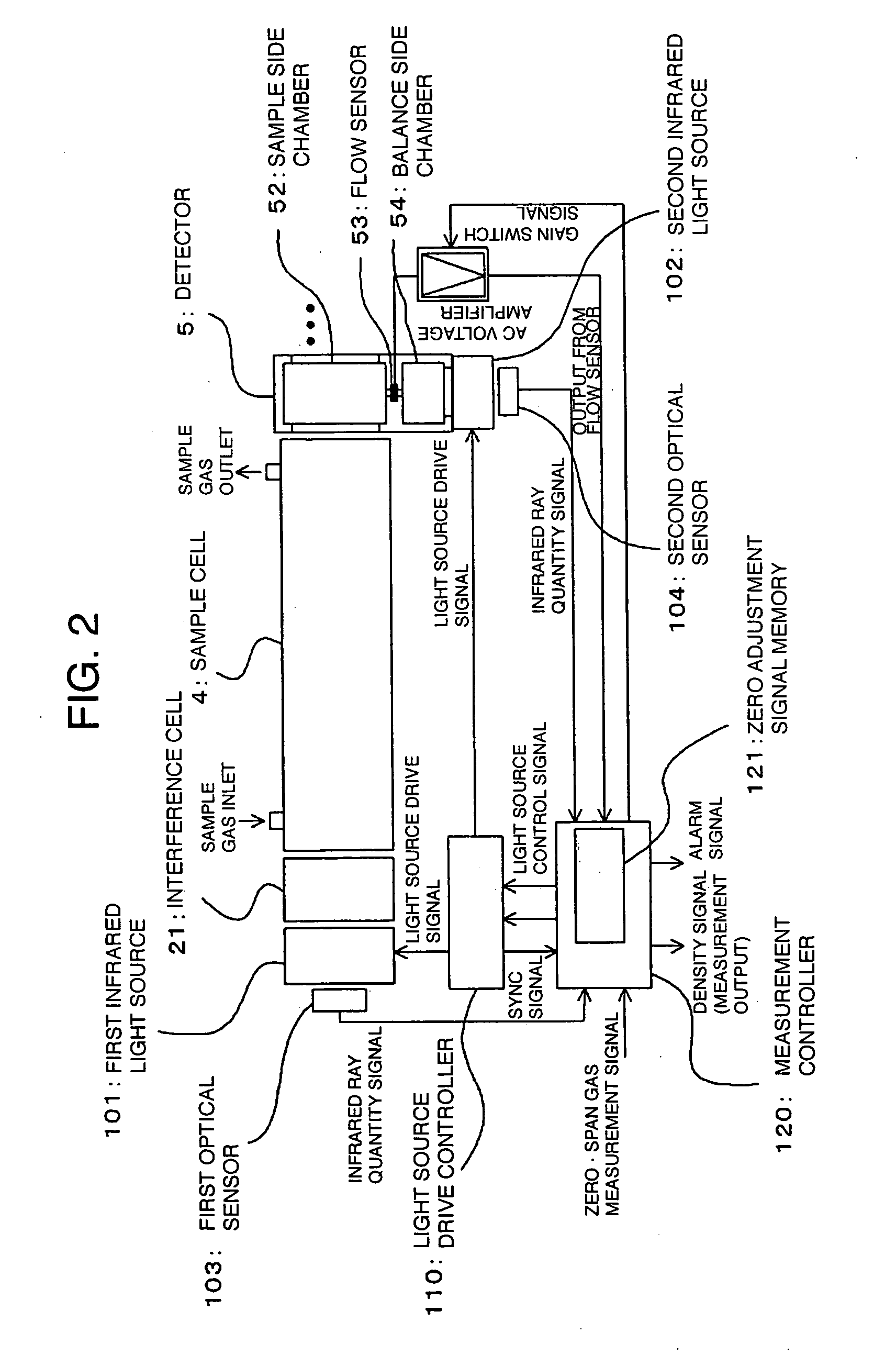
[0044]FIG. 2 is a block diagram showing another embodiment of an infrared gas analyzer, and an infrared gas analysis method using the same, according to the invention. In the figure, parts corresponding to those in FIG. 1 are denoted by like reference numerals. With the present embodiment shown in the figure, a drive amount of a second infrared light source 102 is adjusted at the time of a zero adjustment operation such that a difference between first infrared rays falling on a sample side chamber 52 of a detector 5, via a sample cell 4, and second infrared rays falling directly on a balance side chamber 54 from the second infrared light source 102 becomes zero, and an output of the detector 5 (a flow sensor 53) becomes zero while the drive amount of the second infrared light source 102 is adjusted at the time of a measuring operation as well such that the output of the detector 5 (flow sensor 53) becomes zero, thereby obtaining a measurement output corresponding to concentration of...

embodiment 3

[0047]FIG. 3 is a block diagram showing still another embodiment of an infrared gas analyzer, and an infrared gas analysis method using the same, according to the invention. In the figure, parts corresponding to those in FIG. 1 are denoted by like reference numerals. The present embodiment in the figure shows a specific configuration example of a light source drive controller 110 in FIG. 2 for driving first and second infrared light sources 101, 102, respectively. Reference numeral 113 denotes a synchronous controller for generating a sync signal rectangular in waveform, 111, 112 denote first and second light source drivers, respectively, for generating light source drive signals to be supplied to the first and second infrared light sources 101, 102, respectively, in response to the sync signal and light source control signals impressed from a measurement controller 120, and 105, 106 denote first and second drive signal detectors, respectively, for detecting the magnitudes of the re...


PUM

PropertyMeasurementUnit
concentrationaaaaaaaaaa
concentrationsaaaaaaaaaa
thermal responsivenessaaaaaaaaaa

Abstract

There are provided an infrared gas analyzer of a simple configuration, capable of taking measurements with high precision when using an infrared light source excellent in thermal responsiveness, and capable of ON/OFF operations at high speed, and an infrared gas analysis method using the same. The infrared gas analyzer having a sample cell into which a sample gas is distributed, for detecting concentration of a measuring target component of the sample gas by taking advantage of variation in absorption amount of infrared rays having passed through the sample cell, comprising a first infrared light source for irradiating the sample cell with first infrared rays, a second infrared light source having a response characteristic equal to that of the first infrared light source, a detector for detecting a difference between the first infrared rays emitted from the first infrared light source, and having passed through the sample cell, and second infrared rays emitted from the second infrared light source, a light source drive controller for synchronously driving the first and second infrared light sources, respectively, and a measurement controller for providing the light source drive controller with instructions for respective drive amounts of the first and second infrared light sources while receiving an output signal from the detector, thereby generating a measurement output corresponding to the concentration of the measuring target component of the sample gas.

Description

FIELD OF THE INVENTION [0001] The invention relates to an infrared gas analyzer for detecting concentration of a measuring target component of a sample gas by taking advantage of infrared light ray absorption characteristics of a measuring target gas, and an infrared gas analysis method using the same. [0002] More specifically, the invention is concerned with an infrared gas analyzer capable of executing high-precision measurements with a simple configuration in the case of using light sources excellent in thermal responsiveness, and capable of executing ON / OFF operations at high speed as infrared light sources, and an infrared gas analysis method using the same. BACKGROUND OF THE INVENTION [0003]FIG. 7 is a block diagram showing an example of a conventional infrared gas analyzer. As shown in the figure, infrared light rays emitted from an infrared light source 1 are divided into two infrared light components by a distribution cell 2 to thereby enter a reference cell 3, and a sample...

Claims


Application Information

Patent Timeline
Patent Type & Authority Applications(United States)
IPC IPC(8): G01J5/02G01N21/01G01N21/37
CPCG01N21/37G01N21/3518
Inventor NANKO, TOMOAKIYAMAGISHI, HIDEAKIMATSUMURA, SHIGERU
Owner YOKOGAWA ELECTRIC CORP
Why Eureka
Try Eureka