

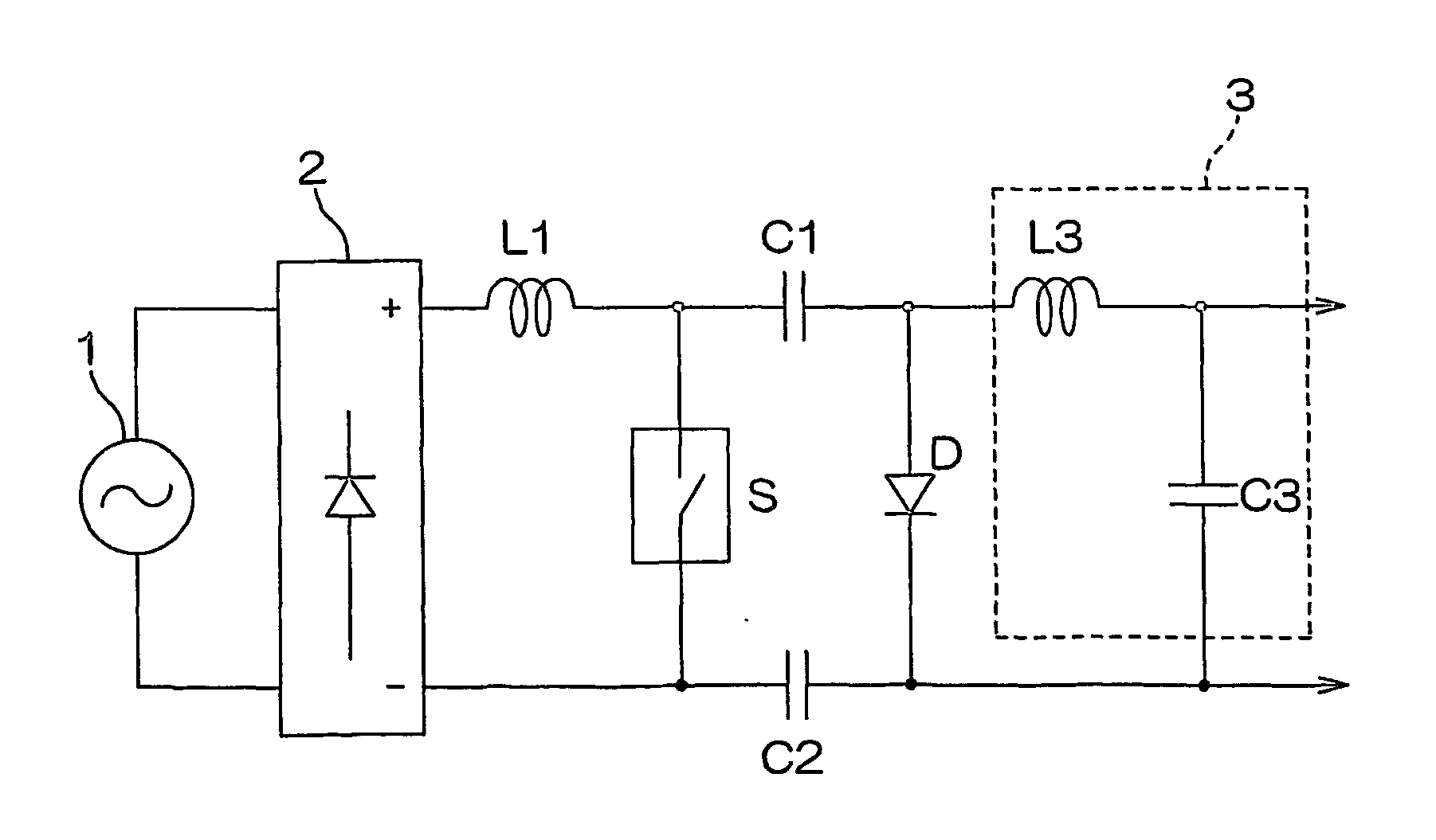
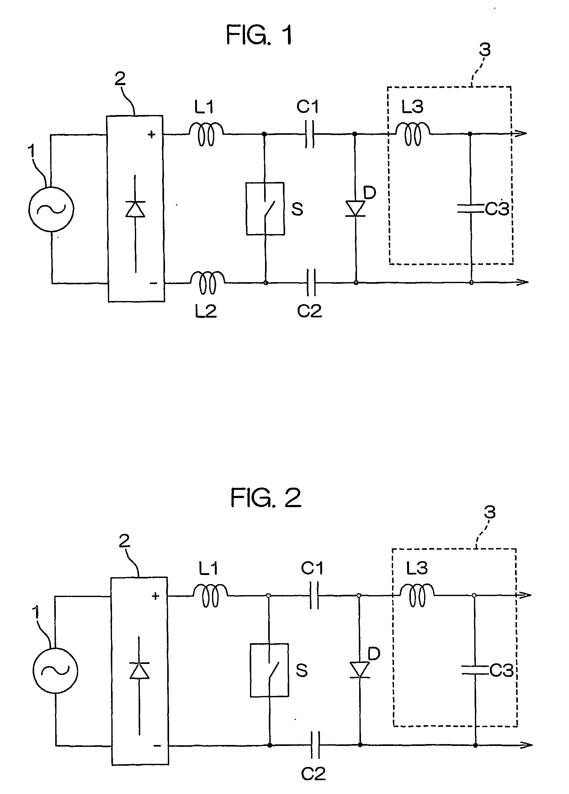
Cuk converter with inductors and capacitors on both power lines
a technology of capacitors and power lines, applied in the direction of dc-dc conversion, power conversion systems, instruments, etc., can solve the problems of general difficulty in power supply apparatus use, inability to ensure a sufficient insulation of alternating current, etc., and achieve the effect of small harmonic distortion on the power transmission or distribution sid
- Summary
- Abstract
- Description
- Claims
- Application Information
AI Technical Summary
Benefits of technology
Problems solved by technology
Method used
Image

Examples
example 1
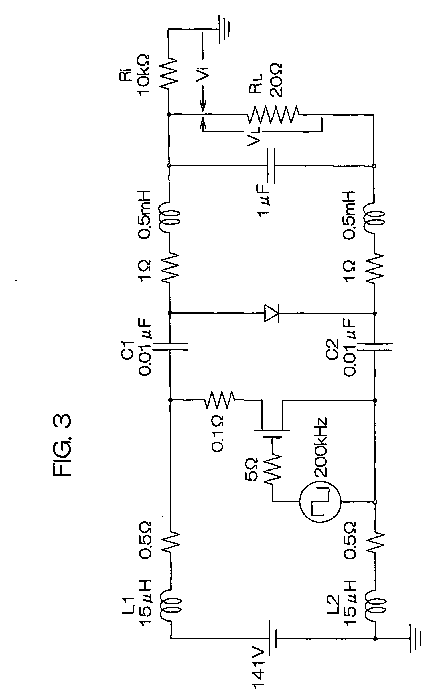
[0038]FIG. 3 is a circuit diagram used for verifying the effect of the present invention. The circuit arrangement and the circuit constants were entered into a computer and the voltages and current waveforms of respective parts were estimated with the use of a circuit analyzing software.
[0039] The circuit in FIG. 3 is of the direct-current-input and direct-current-output type, and the alternating current power supply 1 and the first rectification circuit 2 in FIG. 1 are omitted. There are used coils of 15 μH as members corresponding to the inductors L1, L2, and capacitors of 0.01 μF as members corresponding to the capacitors C1, C2. Accordingly, this circuit satisfies the relationship of L1=L2 and C1=C2. The chopping frequency is 200 kHz.
[0040] A resistance of 20Ω is connected as a load RL. Connected to one end of the load RL is a resistance Ri to be used for investigating the insulation.
[0041]FIG. 4 is a graph illustrating the voltage waveforms, with the passage of time, of the ...
example 2
[0044]FIG. 5 is another circuit diagram used for verifying the effect of the present invention. There are used coils of 10 μH and 20 μH as members respectively corresponding to the inductors L1 and L2, and capacitors of 0.014 μF and 0.007 μF as members respectively corresponding to the capacitors C1 and C2. Accordingly, this circuit satisfies the relationship of L1 / L2=C2 / C1=0.5.
[0045]FIG. 6 is a graph illustrating the voltage waveforms, with the passage of time, of the both-end voltage Vi of a resistance Ri and a load voltage VL after a direct-current electricity has been turned ON.
[0046] As shown in the graph in FIG. 6, likewise in FIG. 4, the load voltage VL quickly rises up after the power has been turned ON, but the voltage Vi remains substantially zero.
PUM
 Abstract
Description
Claims
Application Information