
Optical recording medium and its information recording method, and recorder

Inactive Publication Date: 2006-06-08
NEC CORP
View PDF7 Cites 7 Cited by
  • Summary
  • Abstract
  • Description
  • Claims
  • Application Information

AI Technical Summary

Benefits of technology

[0011] It is an object of the present invention to provide an optical recording medium having address information detectable from both a land and a groove without adversely affecting recording data when both the land and the groove are used as recording tracks, and information recording method and recording unit thereof.
[0012] It is to be noted that the present invention relates to a prepit arrangement for using both the land and the groove as recording tracks. This makes it possible to record the address information in a common format between an optical recording medium using both the land and the groove as recording tracks and a medium using either the land or the groove as a recording track, thereby allowing a common recording method to be used therebetween. This common method aims at using a common circuit concerning address identification and format management by the recording unit to ensure high compatibility between both the media. For this reason, the optical recording medium using only the land or the groove also requires arrangement of the address information compliant with the prepit arrangement on the optical recording medium using both the land and the groove.
[0018] When the land and the groove are both used as recording tracks, the recording medium and the recording method according to the present invention can correctly detect wobble phases on the land and the groove and form prepits as information containing physical addresses detectable from the land and the groove.
[0019] The use of the recording method and the recording unit according to the present invention can protect a prepit forming region with a long mark or a long space. Even a recorded medium enables correct reading of information from a prepit. In addition, it is possible to prevent interference with a reproduced signal from a prepit and prevent a read error from occurring. These effects enable provision of the optical recording medium, the recording method, and the recording unit (or recording / reproducing unit) capable of high-density recording.
[0020] As described in preferred embodiments of the present invention, the long space or the long mark can be selected depending on a frame to be recorded. When a multi-layer medium is used, there is provided an effect of avoiding occurrence of an inter-layer crosstalk resulting from locally concentrating long marks or long spaces.

Problems solved by technology

When both the land and the groove are used as recording tracks on the above-described DVD-R and DVD-RW disks, data recorded on the land is strongly interfered by prepits also recorded on the land.
Thus, correct data reproduction has been difficult.
Consequently, a correct frequency cannot be detected from the recording track on the land.
Even though wobble phases are aligned on the adjacent tracks, however, it is impossible to solve the first problem of interference between a prepit and data on the recording track.
Interference from prepits frequently causes data read errors.
However, it is difficult to modulate the wobble so as to correctly detect the address information from both the land and the groove.
Thus, it is considered that both the land and the groove cannot be used as recording tracks.

Method used


Image

  • Optical recording medium and its information recording method, and recorder
  • Optical recording medium and its information recording method, and recorder
  • Optical recording medium and its information recording method, and recorder

Examples


first embodiment

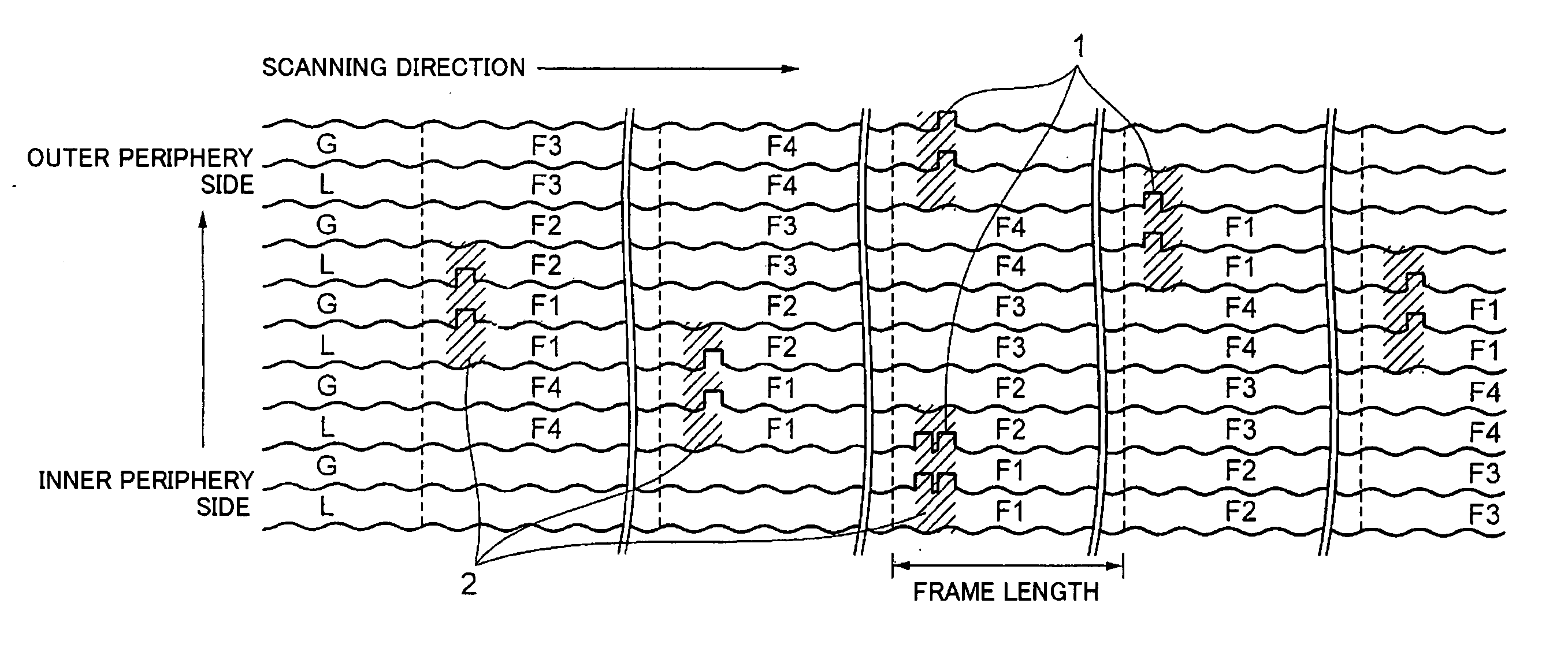
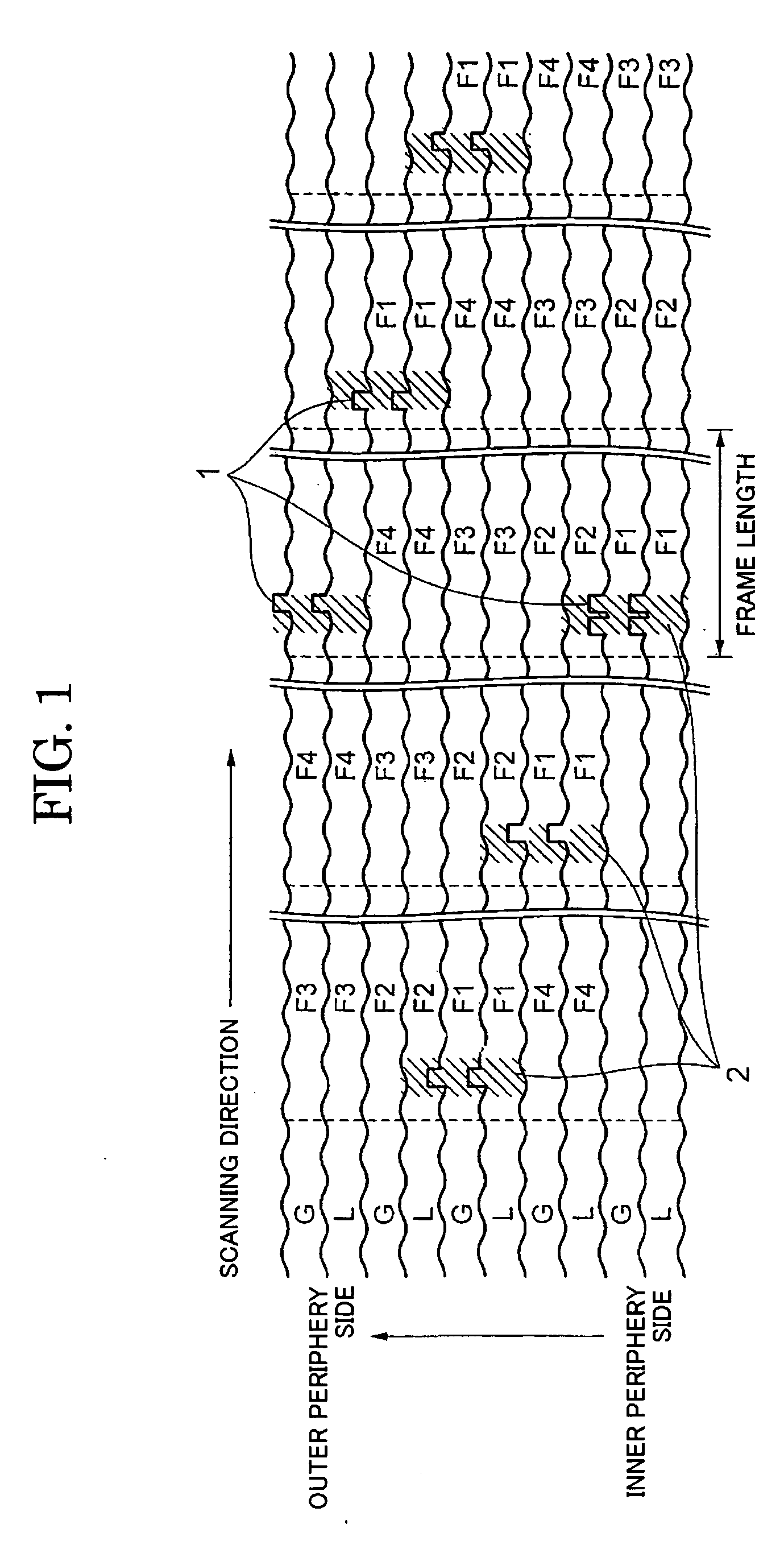
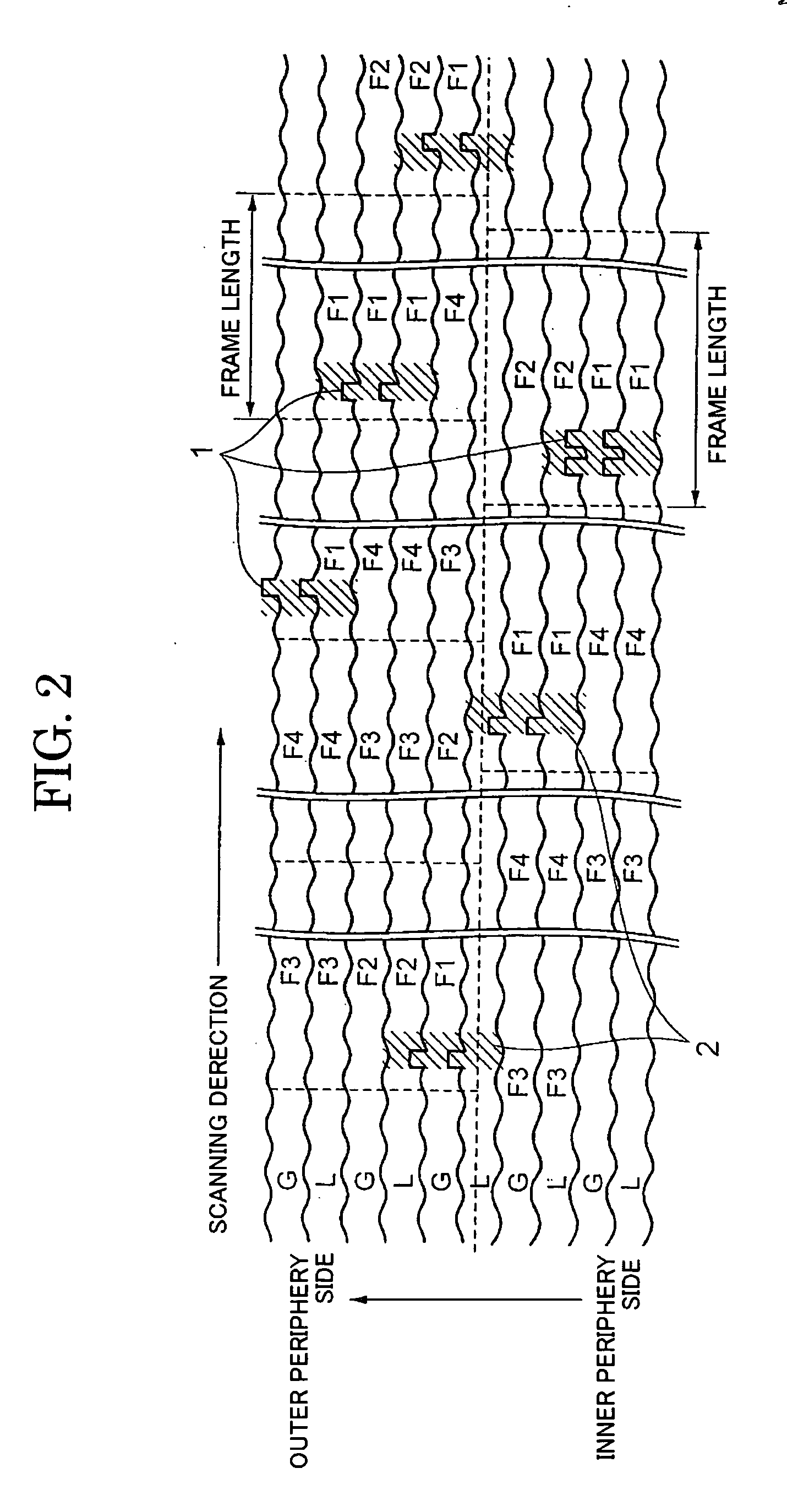
[0040]FIG. 1 shows the arrangement of prepits and wobbles formed on an optical recording medium according to the present invention. Grooves (G) are continuously and spirally formed from the inner periphery to the outer periphery of the disk. The grooves are formed while wobbling at an approximately constant frequency in a radial direction. The grooves disposed adjacent to one another in each zone have the same phase. FIG. 1 is a partially enlarged view of the same zone on the disk formed in this manner. In each zone, the lands (L) each sandwiched between grooves are formed to have a constant track width. For this reason, the following advantages are available. That is, even when the groove and the land are used as recording tracks, an excellent wobble waveform can be detected on both. Reproduced waveforms are hardly subject to an amplitude variation caused by a variation in the recording track width.

[0041] On the groove, frames F1, F2, F3, and F4 are periodically arranged along the ...

second embodiment

[0059]FIG. 9 exemplifies arrangement of prepits and wobbles formed on an optical recording medium according to the present invention. The embodiment presents an example of deforming only a side wall at the groove's outer periphery side as another example of forming prepits by deforming a groove side wall. Such prepits can be formed during exposure on a master disk by radiating a groove exposure beam and a prepit formation exposure beam only at the position for forming a prepit. The prepit formation exposure beam is radiated to a position deviated approximately half a track toward the outer periphery. When a prepit is formed by deforming the side wall only at the outer periphery side, a prepit forming region exists on a land and a groove sandwiching therebetween the deformed side wall. Frame F2 on the groove or frame F4 on the land is not influenced by deformation of the side wall and has no prepit forming region. Data formatted as shown in FIG. 6 can be recorded on the optical recor...

third embodiment

[0061]FIG. 10 exemplifies arrangement of prepits and wobbles formed on an optical recording medium according to the present invention. The example shows formation of prepits by disconnecting the groove. When prepits are formed by disconnecting the groove in this manner, only a groove formation exposure beam can be used to expose a master disk. However, different prepit detection methods must be used for a recording track on the land and a recording track on the groove. FIG. 11 exemplifies waveforms of a sum signal and a difference signal obtained from a bisected detector of the optical head. A recording track on the groove causes a pulse waveform resulting from a prepit to be superposed on the sum signal at the beginning of frame F1 containing the groove disconnection. On the other hand, a wobble waveform appears in the difference signal on which, however, a pulse waveform resulting from a prepit is not superposed. When a mark is formed on the recording medium, the sum signal shows ...


PUM


Abstract

An optical disk includes grooves (G) formed concentrically or spirally from an inner periphery to an output periphery of a disk, wherein prepit (1) are formed on the lands (L) each sandwiched between grooves and grooves (G). The prepit forming region (2) is assigned as a region in which a single or a plurality of prepits (1) are formed. Th prepit forming regions (2) have a fixed length 36 or less times the recording channel length along the recording track, and are arranged apart from on another by 300 or more times the recording channel bit length along the recording track. On the prepit forming region (2), a pattern including a long mark or a long space having a length ten or more times the recording channel bit length so that the long mark or long space covers the prepit (1) on the recording track.

Description

TECHNICAL FIELD [0001] The present invention relates to an optical recording medium, and more particularly, to an optical recording medium having grooves formed concentrically or spirally and prepits formed between and / or on the grooves. The present invention also relates to an information recording method and a recording unit for recording data on such a high-density recording medium. BACKGROUND ART [0002] Known examples of recordable optical disks include DVD-R (Digital Versatile Disc-Recordable) and DVD-RW (Digital Versatile Disc-Rewritable). On these recording disks, a recording track is formed with a fine wobble at a specified frequency (140 kHz). Prepits are provided on a land, wherein decoding of a signal detected from the prepit can determine the position on the disk. [0003]FIG. 15 shows arrangement of prepits and wobbles provided on a DVD-R or DVD-RW disk. Grooves are used as recording tracks. The groove is formed so as to wobble at a specified frequency when the disk is ro...

Claims


Application Information

Patent Timeline
IPC IPC(8): G11B7/24G11B7/0045G11B7/005G11B7/007G11B7/24082G11B7/24085G11B7/24091G11B7/24097
CPCG11B7/0045G11B7/0053G11B7/00718G11B7/00745G11B7/24082
Inventor KAYANUMA, KINJI
Owner NEC CORP
Learn More