Apparatus and methods for incorporating bandwidth forecasting and dynamic bandwidth allocation into a broadband communication system

a technology of dynamic bandwidth allocation and broadband communication system, applied in the field of apparatus and methods for incorporating bandwidth forecasting and dynamic bandwidth allocation into a broadband communication system, can solve the problems of affecting the performance of users on that channel, applications and internet services cannot be adequately provided, and rarely will a single user have available for use a large portion of the entire bandwidth

Inactive Publication Date: 2006-06-08
CISCO TECH INC
View PDF81 Cites 301 Cited by
  • Summary
  • Abstract
  • Description
  • Claims
  • Application Information

AI Technical Summary

Benefits of technology

[0026] In accordance with some aspects of the present invention, a system for controlling network access to a shared communications medium between a plurality of users includes a load balancer operative for allocating users between channels of the shared medium based upon a predicted need. A predictive admission control component arbitrates user requests for access to the shared communications medium in response to predicted aggregate demands, and a lookahead scheduler forecasts schedule transmission opportunities on a given channel. In some aspects of the system, the load balancer changes the channel of communications of a selected user to a channel having a lighter load, and is further operative and predicts congestion parameters for each channel.

Problems solved by technology

A particular channel is congested when overcrowding occurs causing degraded performance to a user on that channel.
It is believed that these new multimedia applications and Internet services cannot adequately be provided for over Dedicated Connection Carrier Networks and that, consequently, Shared Access Carrier Networks ultimately will prevail as the predominant type of Carrier Network for Internet access by users.
Thus, rarely will a single user have available for use a large portion of the entire bandwidth in a particular direction.
Unfortunately, Shared Access Carrier Networks that have been established were designed to provide the traditional Internet services, and not the new multimedia applications and Internet services that require higher throughput rates for acceptable levels of service.
A disadvantage of the revisions to DOCSIS 1.1 is that the revisions do not enhance established Cable Networks constructed with only DOCSIS 1.0 compliant equipment, as such equipment does not support the added functionality of DOCSIS 1.1 so as to distinguish between data packets.
More broadly, another disadvantage of the classification of data packets into Internet Protocol (IP) flows based on the services represented by the data packets is that such classification discriminates against users who do not utilize multimedia applications and services receiving the prioritized transmissions.
At least for some extensive users of the traditional Internet services, some degradation in performance may be noticed by lower classification of their data packets, particularly if the user engages in, for example, web hosting.
While the transmissions of data packets for documents, files, and emails are not as time-sensitive as data packets for voice and video, increased data packet latency for documents, files, and emails, even if incrementally small, nevertheless will result in service degradation for large or numerous documents, files, and emails.
Ultimately, a basic limitation of a cable network is that the separate interests of multiple users simultaneously compete for access to limited bandwidth on a shared medium.
As a result, DOC networks are vulnerable to network congestion that can be causative of degradations in performance being experienced by the users.
The problems of network congestion may require solutions that outpace the computing time required in bandwidth-allocation software applications.

Method used


Image

  • Apparatus and methods for incorporating bandwidth forecasting and dynamic bandwidth allocation into a broadband communication system
  • Apparatus and methods for incorporating bandwidth forecasting and dynamic bandwidth allocation into a broadband communication system
  • Apparatus and methods for incorporating bandwidth forecasting and dynamic bandwidth allocation into a broadband communication system

Examples


Embodiment Construction

[0065] In the following detailed description, numerous specific details are set forth with regard to preferred embodiments of the present invention in order to provide a thorough understanding of the present invention; however, it will be apparent to ordinary artisans that the present invention may be practiced without all of these specific details. Well-known structures and devices also are shown in block diagram form, the specific details of which are not considered a necessary part of the present invention. Furthermore, as will become apparent to ordinary artisans, the present invention may be embodied in or performed by hardware, firmware, or software, or various combinations thereof.

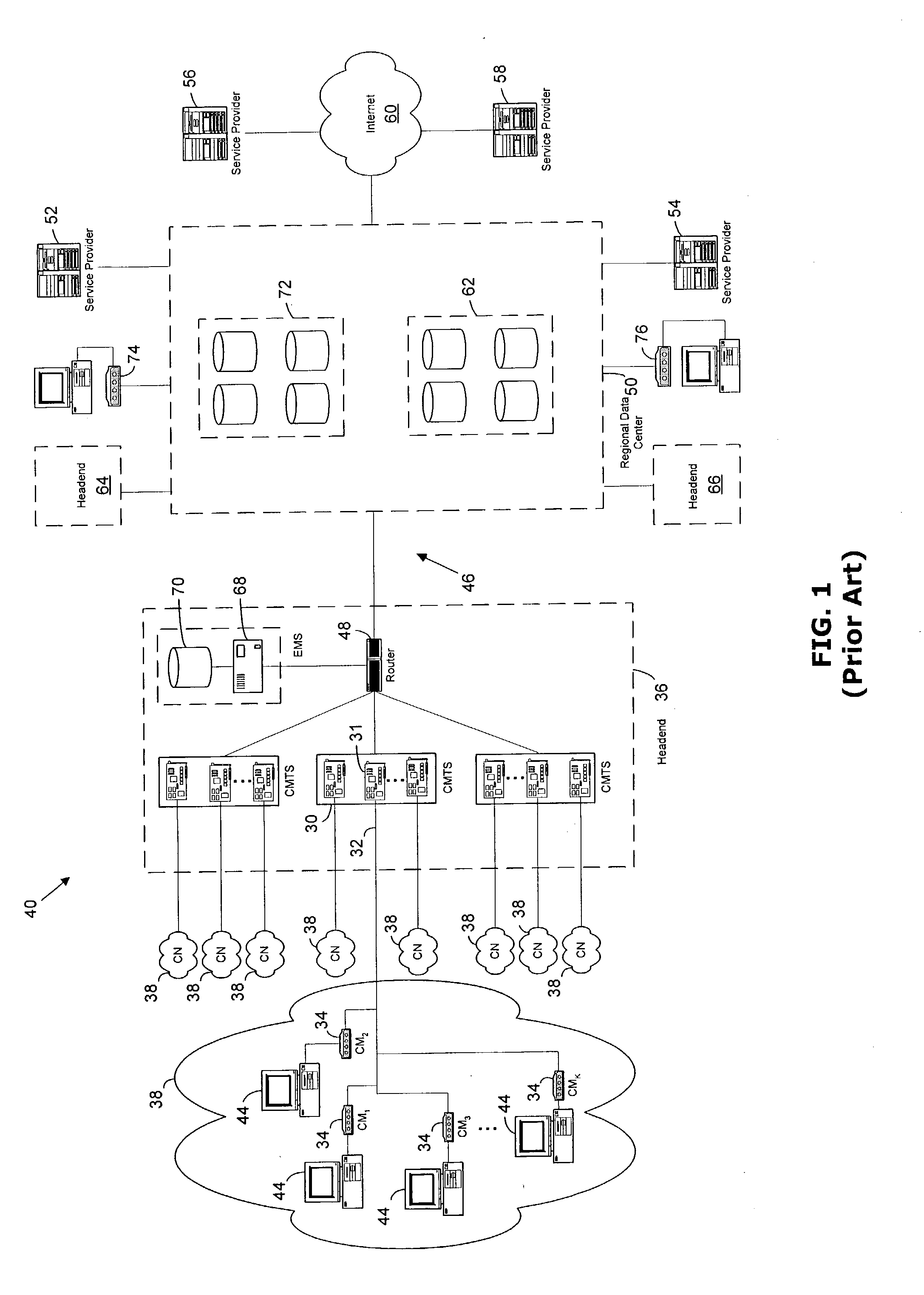
[0066] As described above, a conventional DOC Network 40 is shown in FIG. 1 and includes a plurality of Cable Networks 38, with a particular Cable Network 38 being illustrated in an expanded view and comprising a group of CMs 34, each connected to a computer 44 representing a user. Additionally, as...


PUM


Abstract

A method for providing network access to a shared access communications medium for a plurality of users includes the steps of conducting predictive admission control by arbitrating user requests for access to the shared medium based on predicted aggregate demands, conducting lookahead scheduling for use in making user channel assignments by forecasting schedule transmission opportunities one or more channels of the shared medium, and balancing load by making channel assignments such that a plurality users are each assigned a respective channel of the shared medium based upon a predicted need. Congestion parameters can predicted for each channel of the shared medium and mapped to a congestion measure using a mathematical function that takes into account packet loss rate, packet delay, packet delay jitter, and available capacity.

Description

CROSS REFERENCES TO RELATED APPLICATIONS [0001] This application claims priority under 35 U.S.C. 19(e) to the benefit of the filing date of the McKinnon et al. U.S. Provisional Patent Application Ser. No. 60 / 371,213, filed on Apr. 9, 2002, which is incorporated herein by reference and made a part hereof. This application is a Continuation in Part of and claims priority under 35 U.S.C. Section 120 to the benefit of the filing date of the McKinnon et al. U.S. Non-Provisional patent application Ser. No. 09 / 800,674 filed Mar. 7, 2001, entitled “Allocating Access Across a Shared Communications Medium” which is incorporated herein by reference and made a part hereof and which claims priority under 35 U.S.C. 119(e) to the benefit of the filing date of the McKinnon et al. U.S. Provisional Patent Application Ser. No. 60 / 205,963 filed on May 19, 2000, which is incorporated herein by reference and made a part hereof. This application incorporates herein by reference and makes parts hereof each...

Claims


Application Information

Patent Timeline
Patent Type & Authority Applications(United States)
IPC IPC(8): H04L12/26H04J1/00H04L12/28
CPCH04L12/2602H04L12/2801H04L12/2856H04L12/2861H04L12/2865H04L12/2876H04L12/5695H04L41/0896H04L41/147H04L41/5003H04L41/5009H04L41/5019H04L41/5022H04L41/5029H04L41/5067H04L41/5087H04L41/509H04L43/00H04L43/022H04L43/045H04L43/06H04L43/062H04L43/067H04L43/0829H04L43/0882H04L43/0888H04L43/106H04L43/12H04L43/16H04L45/245H04L47/10H04L47/11H04L47/12H04L47/125H04L47/127H04L47/15H04L47/20H04L47/24H04L47/263H04L47/28H04L47/29H04L47/41H04L47/762H04L47/788H04L47/805H04L47/808H04L47/822H04L47/823H04L47/824H04L47/826H04L47/828H04N7/17309H04N21/2385H04N21/2408H04N21/6118H04N21/64738Y02B60/33H04L47/70Y02D30/50H04L47/83
Inventor CARLSON, WILLIAM S.MOYER, MATTHEW JAMESMCKINNON, MARTIN WILLIAM IIIRUFUS, FREEMAN JR.HART, JOHN BRADFORD
Owner CISCO TECH INC
Why Eureka
Try Eureka