Tandem type trochoid pump and method of assembling the same

a trochoid pump, tandem technology, applied in the direction of machines/engines, rotary/oscillating piston pump components, liquid fuel engines, etc., can solve the problem of large housing of the pump, and achieve the effect of avoiding upsizing the pump and improving the workability

Inactive Publication Date: 2006-06-08
HITACHI LTD
View PDF5 Cites 13 Cited by
  • Summary
  • Abstract
  • Description
  • Claims
  • Application Information

AI Technical Summary

Benefits of technology

[0005] It is therefore an object of the present invention to provide a tandem type trochoid pump which improves a workability during an assembly process of the pump while avoiding upsizing of the pump.

Problems solved by technology

However, such a known tandem type pump has had a problem that a housing of the pump becomes large due to the using of the intermediate casing.

Method used


Image

  • Tandem type trochoid pump and method of assembling the same
  • Tandem type trochoid pump and method of assembling the same
  • Tandem type trochoid pump and method of assembling the same

Examples


Embodiment Construction

[0025] Hereinafter, there is discussed a best mode of the present invention, on the basis of a first embodiment.

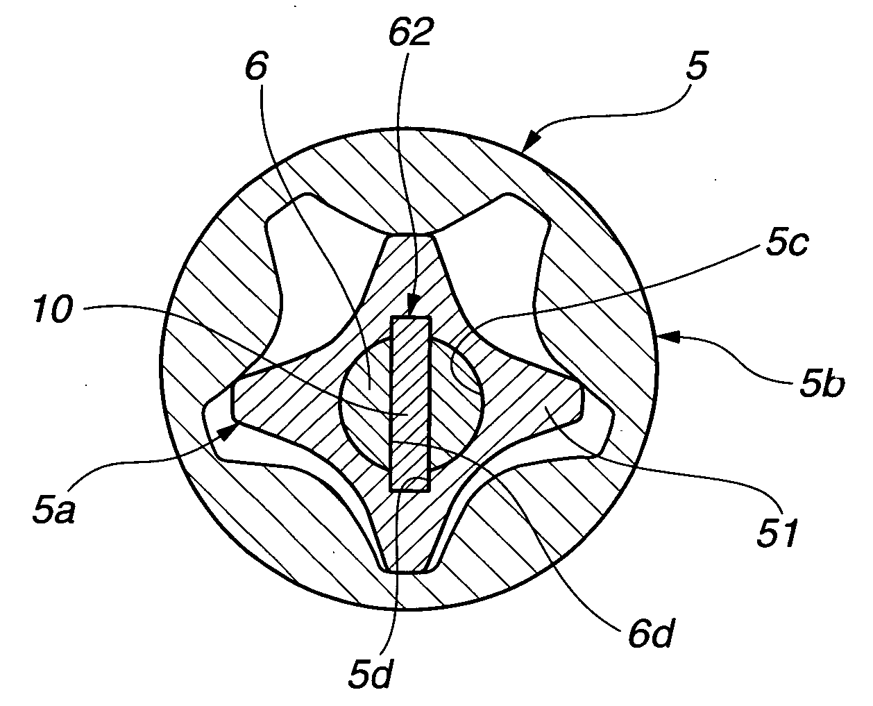
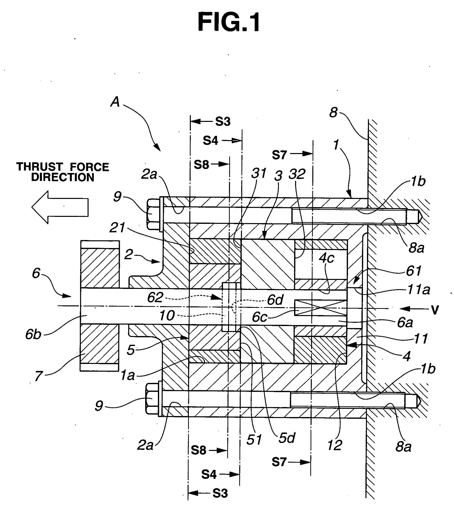
[0026]FIG. 1 is a longitudinal cross-sectional view showing a construction of a tandem type trochoid pump (tandem type inscribed gear pump or tandem rotor-type pump) according to a first embodiment of the present invention. FIG. 2 is a view taking in the direction V of FIG. 1. The first embodiment exemplifies the application of the tandem trochoid pump A according to the present invention to a lubrication oil pump for an internal combustion engine.

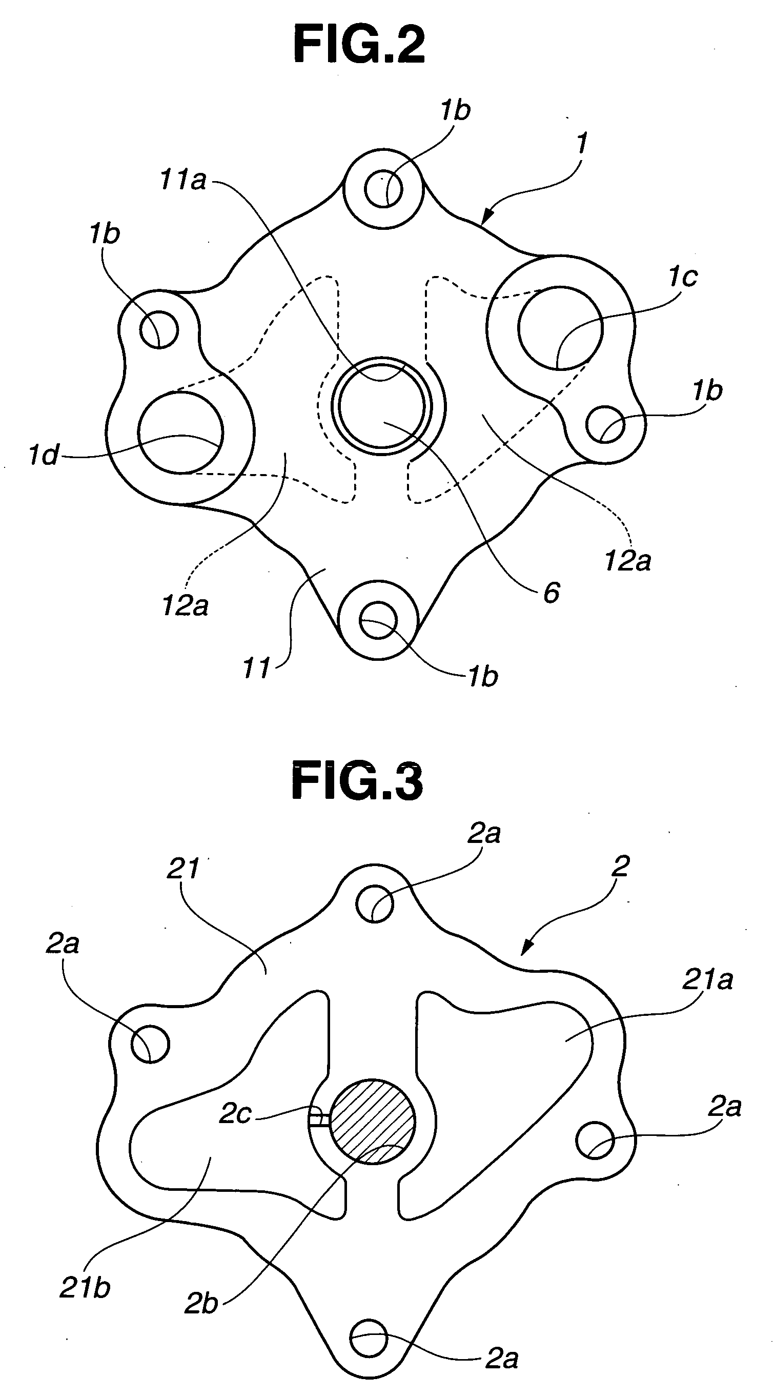
[0027] Tandem type trochoid pump A of the first embodiment comprises a housing body 1, a comp cover 2, a spacer 3, a first trochoid pump (first inscribed gear pump) 4, a second trochoid pump (second inscribed gear pump) 5, a drive shaft 7, and a helical gear 7.

[0028] Housing body 1 is formed into a cylindrical shape. Housing body 1 has an opening portion 1a at an end near helical gear 7 and a bottom portion 11 at the other end...


PUM

PropertyMeasurementUnit
rotational angleaaaaaaaaaa
cylindrical shapeaaaaaaaaaa
rotational forceaaaaaaaaaa

Abstract

A tandem type trochoid pump is comprised of a drive shaft having a non-circular end portion, a spacer portioning a first trochoid pump and a second trochoid pump in a housing body, a first fixing portion for fixing a first inner rotor of the first trochoid pump to the drive shaft in rotational direction, and a second fixing portion for fixing a second inner rotor of the second trochoid pump to the drive shaft in rotational direction.

Description

BACKGROUND OF THE INVENTION [0001] The present invention relates to a tandem type trochoid pump employing two sets of trochoid pumps and a method of assembling the tandem type trochoid pump. [0002] Japanese Published Utility Model No. 3-5990 has proposed a tandem type trochoid pump which is arranged to drive two trochoid pumps by applying a rotational force to a drive shaft of the pump. The two trochoid pumps are set such that a timing of communicating an operation chamber and a discharge port of one pump is differentiated from a timing of the other pump, in order to decrease a pulse pressure of the oil pump. [0003] Since two inner rotors of the two pumps are arranged so as to integrally rotate with the drive shaft, it is difficult to respectively install the two inner rotors having different phases into corresponding outer rotors. In order to solve this difficulty, Japanese Published Utility Model No. 3-5990 has employed an intermediate casing for sub-assembling one of the two pump...

Claims


Application Information

Patent Timeline
Patent Type & Authority Applications(United States)
IPC IPC(8): F01C1/02F16N13/20F01C1/063F04C2/00F03C2/00F04C18/00F03C4/00
CPCF04C2/102F04C11/001Y10T29/49236F04C2230/60F04C15/0073
Inventor OHNISHI, HIDEAKIWATANABE, YASUSHI
Owner HITACHI LTD
Why Eureka
Try Eureka