
Connector

a technology of connecting rods and connectors, applied in the direction of material analysis, coupling device connections, instruments, etc., can solve the problems of high voltage damage to the electrical apparatus connected to the connecting rods, and achieve the effect of improving the quality of the switch part and improving the on-off accuracy of the switch

Active Publication Date: 2006-06-08
ARKRAY INC
View PDF7 Cites 81 Cited by
  • Summary
  • Abstract
  • Description
  • Claims
  • Application Information

AI Technical Summary

Benefits of technology

[0021] The present invention constructed as the above brings the following effects. According to the present invention, with regard to a connector having a switch part comprising a rocking terminal swayed by inserting an insertion into a main body of the connector and a receiving terminal arranged to contact the rocking terminal, a pointed part is formed on the rocking terminal, and the terminals contact electrically with each other by making the receiving terminal touch a side surface of the pointed part. Accordingly, foreign matters are never accumulated on the side surface of the pointed part so as to keep the contact part clean always, whereby contact failure is prevented so as to ensure the electrical contact.
[0022] With regard to the connector of the present invention, the receiving terminal is provided at a position opposite to the rocking terminal, the pointed part of the rocking terminal is constructed acutely, an engaging part is provided on the receiving terminal at a position opposite to the pointed part, and the terminals contact electrically with each other by making the engaging part and the pointed part engage with each other. Accordingly, even if foreign matters adhere to the pointed part, the foreign matters fall down through the engaging opening by inserting the pointed part into an engaging hole as the engaging opening, it cause the electrical contact to be ensured.
[0023] According to the present invention, with regard to a connector having a switch part comprising a rocking terminal swayed by inserting an insertion into a main body of the connector and a receiving terminal arranged to contact the rocking terminal, a part of the rocking terminal slidingly contacting the insertion inserted into the connector and a par

Problems solved by technology

Furthermore, by inserting the insertion 2, high voltage static electricity generated at the outside may flow into the rocking terminal 1 (11) through the insertion 2, whereby the high voltage may damage electric apparatus connected to the connector 3.

Method used


Image

  • Connector
  • Connector
  • Connector

Examples


third embodiment

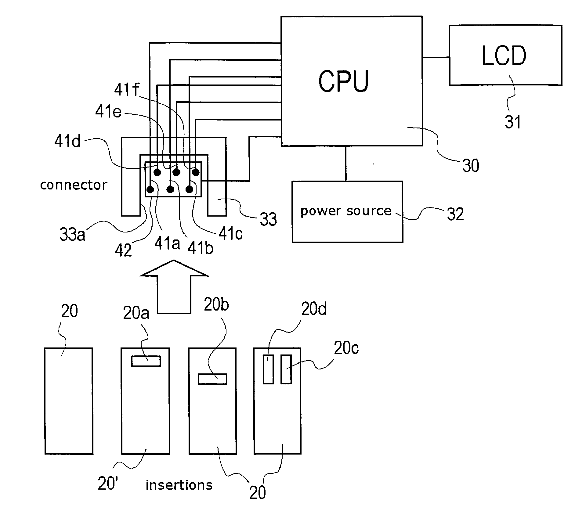
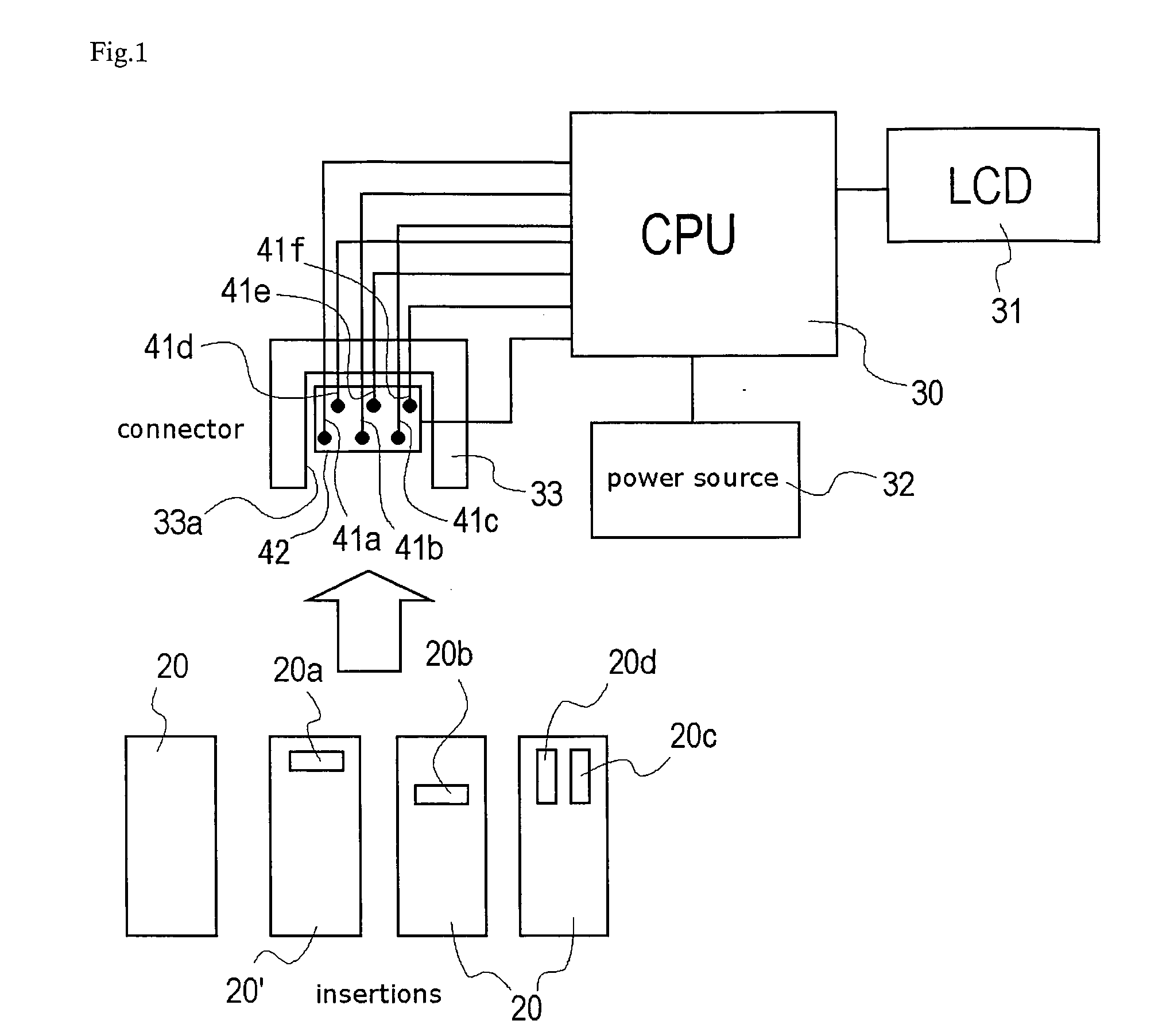
[0057]FIG. 3 is a drawing of the third embodiment that a connector having the switch construction of the present invention is used in a simple blood glucose level measuring device, and FIG. 4 is a drawing of a biosensor 23 as an insertion inserted into the simple blood glucose level measuring device in FIG. 3. The simple blood glucose level measuring device is always carried by a diabetic so as to check the blood glucose level simply for judging whether dosage of insulin is required or not, and whether the diabetic is in low blood glucose or not.

[0058] For measuring the concentration of a specified component in body fluid, such as glucose in blood, there is a general method that uses oxidation-reduction reaction with redox enzyme as a catalyzer. On the other hand, for measuring the blood glucose level simply at home or the place where a diabetic has gone, a hand-held simple blood glucose level measuring device is commonly used. Oxidation reaction is performed in the simple blood glu...

first embodiment

[0071] Explanation will be given on the construction of the switch part in the connector of the present invention according to FIG. 5.

[0072] The switch part comprises a rocking terminal 51 swayed vertically by inserting an insertion 53 and a receiving terminal 52 contacting the rocking terminal 51 normally, and the terminals are projected upper and lower parallel with each other from the main body of the connector. The rocking terminal 51 is constructed by electrically-conductive and elastic material, such as spring steel, and the basal end of the rocking terminal 51 is fixed to the main body of the connector and connected to the controller (or electrical apparatus) through wiring. An pointed part 51a is formed at the tip of the rocking terminal 51, and an inclined part 51b for guiding the insertion and an inclined part 51c for guiding the drawing are formed on the side of the pointed part 51a. In this embodiment, the inclined parts are formed by bending the tip of the rocking termi...

second embodiment

[0080] Next, explanation will be given on the construction of the switch of the present invention according to FIG. 6.

[0081] The switch part comprises the rocking terminal 51 and a receiving terminal 56, and the rocking terminal 51 is constructed the same as that of the first embodiment. The receiving terminal 56 is constructed by an electrically-conductive plate, such as steel plate, and is disposed below the rocking terminal 51 oppositely. The basal end of the receiving terminal 56 is connected to the controller (or electrical apparatus), and an engaging hole 56a is opened at the position corresponding to the pointed part 51a of the rocking terminal 51. Normally, the lower portion of the pointed part 51a is inserted partially into the engaging hole 56a, and the inclined part 51b for guiding the insertion and the inclined part 51c for guiding the drawing of the pointed part 51a contact the upper inner perimeter of the engaging hole 56a.

[0082] In this construction, by inserting the...


PUM


Abstract

In a connecter, the position at which a pointed part of a rocking terminal slidingly contacts an insertion and the position at which the pointed part of the rocking terminal contacts an upper surface of a terminal plate are substantially the same. Therefore, shavings generated by the contact of the insertion and the pointed part or foreign matters adhering to the insertion may adhere to the pointed part of the rocking terminal and be pinched between the pointed part and the terminal plate, whereby no contact is caused by inserting the insertion into the connector. Then, with regard to a connector having a switch part comprising a rocking terminal 51 swayed by inserting an insertion 53 into a main body of the connector and a receiving terminal 52 arranged to contact the rocking terminal, an pointed part 51a is formed on the rocking terminal, and the terminals contact electrically with each other by making the receiving terminal touch a side surface of the pointed part.

Description

TECHNICAL FIELD [0001] The present invention relates to a connector having a switch construction that terminals contacting with each other are provided in the connector, and the terminals are turned into contact or no contact by inserting an insertion into the connector. [0002] Concretely, the present invention relates to an art of a connector, which has a switch part constructed by providing a plurality of terminals contacting with each other in the connector so as to identify insertions inserted into the connector by the switch part turned on or off by inserting an insertion, for preventing contact failure and the like caused by foreign matters at the contact part. BACKGROUND ART [0003] Conventionally, a switch construction may be provided in a connector connecting electronic members or electric apparatus. With regard to the switch construction, two switch terminals are short-circuited (contacted) with each other and provided in the mold of the connector. By inserting an insertion...

Claims


Application Information

Patent Timeline
IPC IPC(8): H01R29/00H01H27/00H01R13/703
CPCH01H27/002H01R13/7031G01N27/3273
Inventor KASAI, TOKUO
Owner ARKRAY INC
Features
  • Generate Ideas
  • Intellectual Property
  • Life Sciences
  • Materials
  • Tech Scout
  • Unparalleled Data Quality
  • Higher Quality Content
  • 60% Fewer Hallucinations
Learn More