Automatic transmission and gear train

Inactive Publication Date: 2006-06-08
KEYBANK NAT ASSOC AS AGENT
16 Cites 9 Cited by

AI-Extracted Technical Summary

Problems solved by technology

This severely limited the overall speed range of the vehicle and therefore required a relatively large engine that could produce a wide speed and torque range.
This resulted in increased engine wear and tear and reduced engine efficiency.
High vehicle down time due to inherent original transmission design problems have been plaguing this fleet for many years.
The lack of controlled testing and evaluation of the 700R4 transmission resulted high failure rates in the field.
Planetary gear wear or tooth breakage.
Torque converter fails.
The 180C transmission as used by the Postal Service, and in other applications which require a great deal of stop and go driving, does not see such ideal usage.
The spalling of the gears results in very small yet very hard pieces of steel flaking off the pressure angle surface of each pinion gear.
As the contaminated oil is pumped to all critical areas of the transmission, these pieces of metal act as an abrasive to all parts they contact.
As gear deterioration progresses the hard steel particles become more concentrated in the oil and become lodged in the valves of th...

Method used

[0073] Metal particles are generated by the rotary motion of the inner and outer gear that creates the volume of oil that results in the necessary oil pressure to operate and sustain the transmission. In order to prevent the creation of metal particles from the oil pump, the inner and outer gear must be kept in their proper position so the motion of the outer gear does not improperly mesh with the inner gear. The inner gear is held in place by the converter hub and the converter hub bushing that is located in the bell housing. If either of these parts are not straight (greater than 0.002″ TIR) the inner gear will cause a problem. The problem of inner gear support is discussed as part of the proper remanufacture of the torque converter and the bell housing that follows. The support of the outer gear is another problem. The natural action of the two gears is to move away from one another in the area of the pressure port. Thus, the outer gear has a tendency to move to the left and the inner gear moves to the right. The outer and inner gears are constructed of powder metal and the pump housing is constructed of iron. The outer diameter of the outer gear is in constant contact with the pump housing. Over time, the outer diameter of the outer pump gear begins to wear into the pump housing. This action creates metal particles in much the same manner as the pinion gears. In order to prevent this, the pump used in the 280PS™ transmission system has a SAE 660 bronze sleeve inserted in the housing in the area of the outer gear. The bronze sleeve is machined to the proper clearance for the outer gear and forms a perfect wear surface that will assure long and sustained performance.
[0074] The tips of the inner pump gear teeth contact the leading edge of the inner diameter of the pump crescent as the bell housing bushing wears. When this undesirable interference occurs between inner pump gear teeth and the pump crescent, noise and small metal particles are generated. The noise is unacceptable from an operational perspective and the metal that is generated as a result of the interference is detrimental to the longevity of the transmission. Both of the above mentioned problems are eliminated by modifying the geometry of the inner pump crescent. The pump of the transmission of the instant invention has the pump crescent inner diameter changed to remove both the noise and eliminates the creation of metal particles generated by the inner pump gear contacting the crescent inner diameter. The new geometry of the inner crescent creates 0.060″ clearance between the inner gear and the leading edge of the inner pump crescent (initial point of contact) and decreases to 0.000″ in a consistent arc 60 to 65 degrees from the initial point of generation. In so doing the tips of the teeth of the inner gear can not contact the leading edge of the inner pump crescent yet by design will still contain the oil within the inner pump crescent which maintains all the previous oil pumping capacity that the pump was designed to create. This new design thus eliminates both the noise and the generation of metal particles, contributing to the overall longevity of the transmission. See FIG. 27.
[0075] The oil pressure generated by the pump is regulated by the pressure regulator valve which is preloaded by the pressure regulator spring. The combination of these two parts working in conjunction with the vacuum modulator (which senses engine load) and the transmission governor (which senses vehicle speed) creates the appropriate oil pressure required to hold all clutches from slipping and produce oil to lubricate and cool the total transmission during operation. The USPS's unique application of this transmission requires the lubrication oil to be regulated in the first and second gear ranges, where it spends most of its operating life, in such a way as to supply oil to lubricate the gear train and prevent the deterioration of meshing components. It was observed during root cause analysis that lubrication oil pressures varied greatly in the transmission. The cause was determined to be the pressure regulator spring creating significantly different preload pressures on the pressure regulating valve. This resulted in either a surplus of lubrication oil or a deficiency of lubrication oil. The new design pressure regulator spring incorporated in the 280PS™ pump uniformly preloads the pressure regulator valve thus assuring correct and uniform oil pressure which maintains correct clutch pressure and lubrication oil flow.
[0076] It was observed through root cause analysis that even with consistent pressure regulation of the transmission oil pump that under certain extreme conditions the oil supplied to the transmission gear train and the torque converter was severely reduced or cut off completely. Both of these conditions created high wear conditions which reduced the life of the transmission. In order to prevent the reduction or loss of lubrication oil, a new method of supplying oil to the critical lubrication circuit had to be created that would supply lubrication oil to the transmission under any condition. This problem was solved by re-engineering the oil lubrication circuit to allow a constant flow of oil form the pressure port to the lubrication port without the influence of the pressure regulation system. A passage (equal to 0.040″) was created between the pressure port of the pump, before regulation, and the lubrication circuit. In so doing, lubrication oil was assured under all conditions guaranteeing adequate lubrication and cooling to critical components and thus extending the life of the transmission. See FIG. 27.
[0077] It was observed through root cause analysis that the inner gear of the transmission pump would move, over time, due to the wear of the bell housing bushing. The wear of the bushing allowed the converter hub and the inner pump gear to move in the direction of the leading edge of the pump crescent and thus create noise and metal to metal contact. In order to reduce the possibility of such an occurrence, the center of the bell housing bushing was moved in the opposite direction and in the same distance of the measured wear. The new position of the bell housing bushing center is a function of the distance off center in relation to the alignment dowels located on the bell housing which are used to align the entire transmission to the engine. During transmission operation the pressure created within the transmission oil pump pushes the inner gear and the converter hub off center by the amount of clearance that exists between the converter hub and the bell housing bushing, minus the oil film created between the two. When this misalignment occurs, all the corresponding parts that depended on the alignment of the bell housing bushing experienced misalignment by the same amount (0.002″ to 0.005″). The bell housing bushing bore should be on center with the crankshaft center which is correspondingly on center with the transmission pump inner gear. When the pressure created inside the pump is exerted on the inner gear and the torque converter hub, the center line of these parts is forced off center during operation. When normal wear was added to this equation the misalignment was magnified adding to premature transmission failure. The new bell housing design moves the center line of the bell housing bushing 0.0025″ off center in the opposite direction of pressure, thus when the pump pressure is exerted on the pump gear and converter hub the entire assembly of associated parts achieves alignment during operation.
[0078] This new alignment design removes the accumulative misalignment that previously existed between the tolerance fits required between the converter hub and the inner pump gear, the tolerance fit required between the pump stator shaft spline and the torque converter stator sprag race, the tolerance fit required between the transmission input shaft spline and the torque converter turbine spline and the tolerance fit required between torque converter nose pilot and the engine crankshaft torque converter pilot hole. This new design achieves operational alignment which reduces the wear on all affected components, thus reducing metal particle generation to the greatest extent possible and extending transmission life of the 280PS™. See FIG. 28.
[0079] If kept free of contamination the valve body will conceivably function indefinitely. However, when contamination occurs, some of the components will wear. The point of wear is the 2/3-boost sleeve, which is made of aluminum. The transmission of the instant invention has a new design boost sleeve installed in this position that is especially designed for this application. The geometry of the boost sleeve has been changed to allow more oil to react to the shifting lands of the shift valve. In so doing the valve is more sensitive, and produces a more repeatable point of shift. The material from which the boost sleeve was made is still aluminum but the alloy is changed to 5056 in order to increase wear resistance and reduce the binding affects that small particles of metal create on the inner shift valve. The leading edges of the valve sleeve are very sharp by design and function as wipers to the valve spool in much the same way that any oil seal protects the inner parts of a mechanism form external dirt contamination. By increasing the valve sleeve's resistance to wear the sharp edges are maintained for a longer period of time during contamination. This new 2/3 shift valve spool will extend the life of the transmission even after metal contamination begins by keeping the small abrasive metal particles from getting betwe...

Benefits of technology

[0014] A further embodiment of the instant invention contemplates a complete transmission sys...

Abstract

The present invention relates to automatic transmissions. In particular, the instant invention relates to an automatic transmission with improved resistance to deterioration with an increased effective life. The transmission of the instant invention comprises eight pinion gears assembled into one carrier utilizing a forward and a rear sun gear, a ring gear, a band drum and a one way roller clutch.

Application Domain

Toothed gearingsGear lubrication/cooling +2

Technology Topic

VariatorEngineering +5

Image

  • Automatic transmission and gear train
  • Automatic transmission and gear train
  • Automatic transmission and gear train

Examples

  • Experimental program(2)

Example

EXAMPLE 1
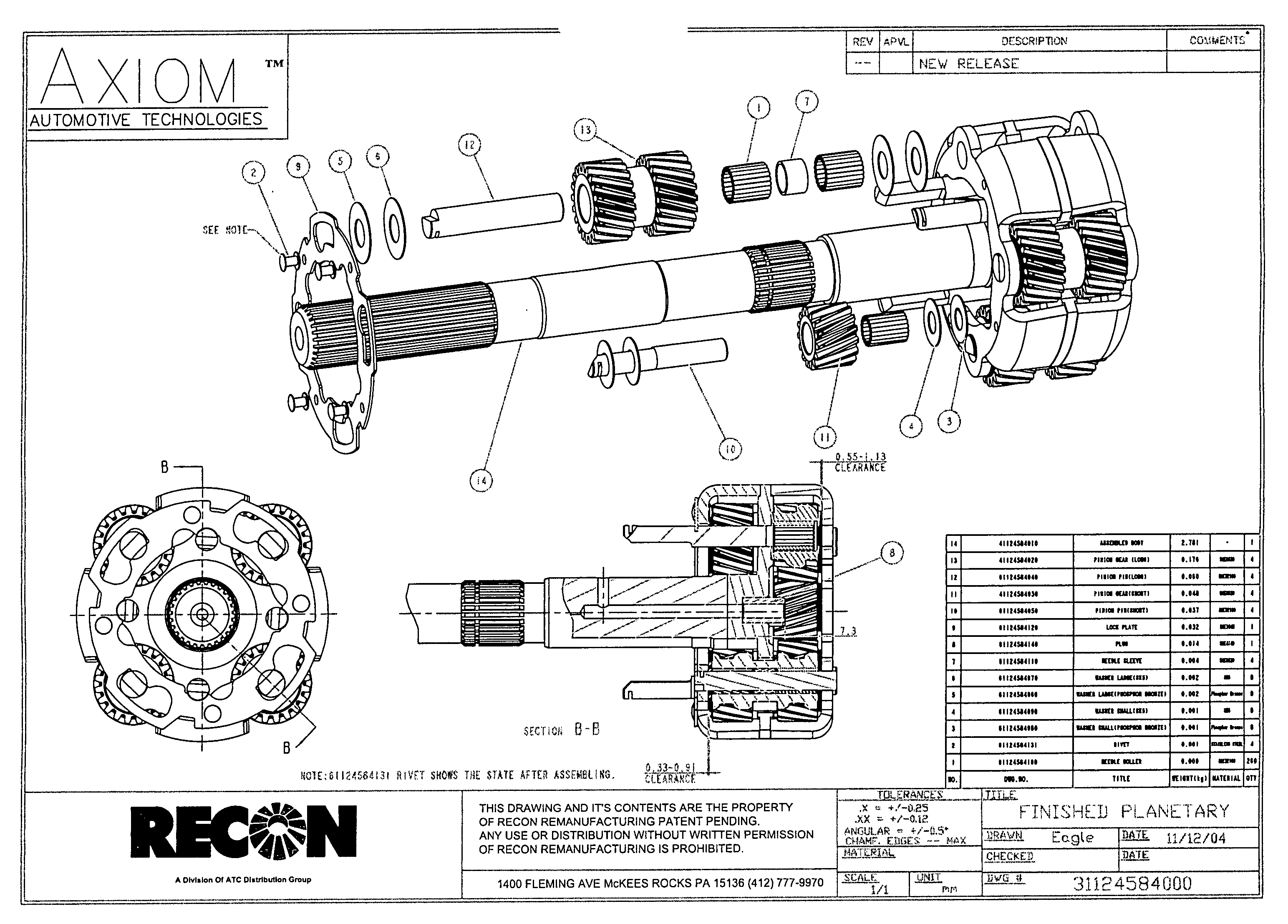
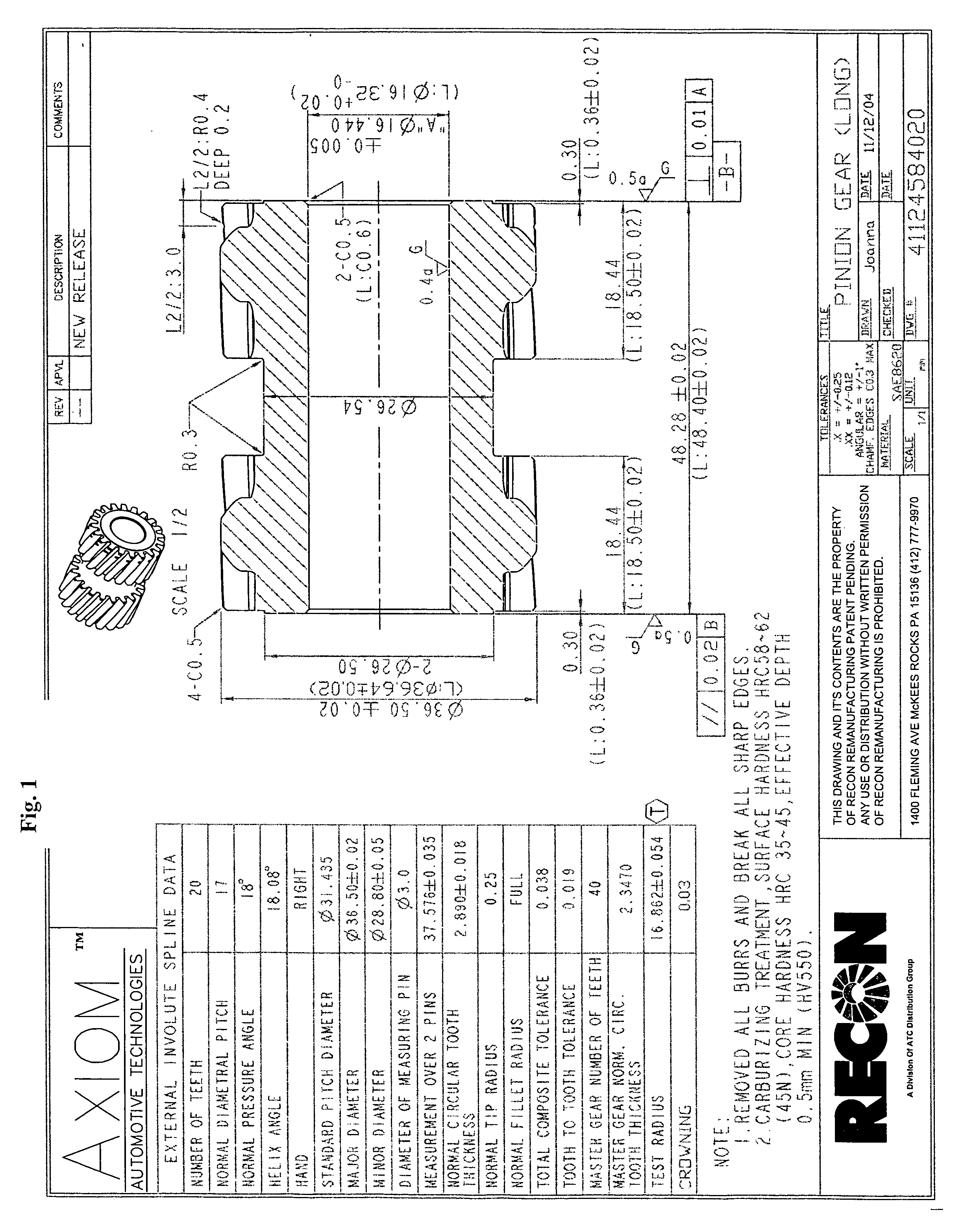
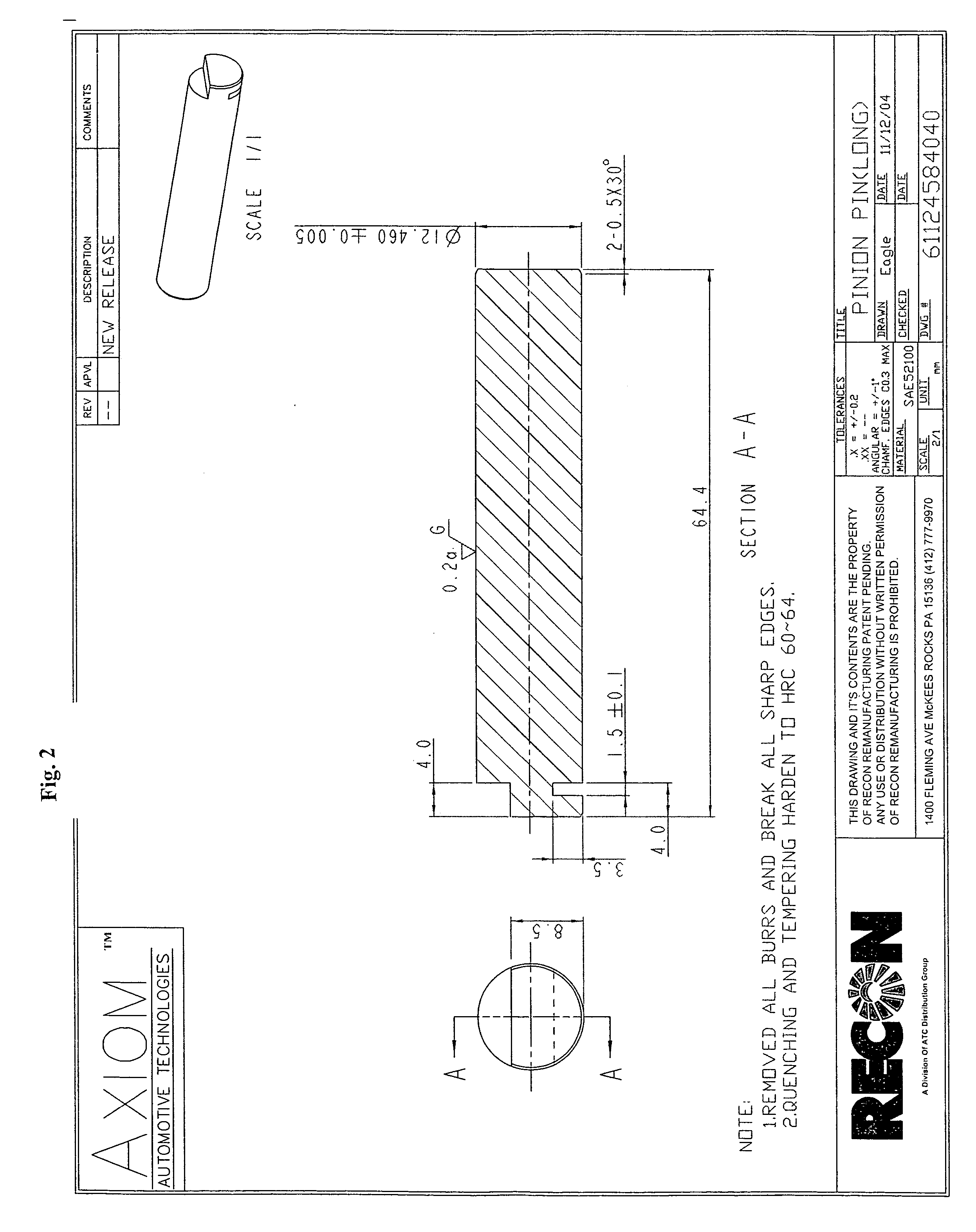
[0136] The disclosed planetary gear train is compound in nature. The transmission is composed of eight pinion gears, four of which are compound, and four that are plain, all eight gears are assembled into one carrier utilizing a forward and a rear sun gear, a ring gear, a band drum and a one way roller clutch. The four plain pinion gears mesh with the four compound gears and the forward sun gear and one way roller clutch. The four compound pinion gears also mesh with the four plain pinion gears, the front sun gear, the ring gear and the rear sun gear. A 2.8 reduction is achieved by applying the rear band and driving the planetary assembly by the front sun gear through the one way roller clutch. (First gear) A 1.8 reduction is achieved by applying the intermediate clutch, thus driving the planetary by the ring gear and over running the one way roller clutch. (Second gear) Third gear is achieved (one to one) by applying the direct clutch, and releasing the rear band maintaining the application of the intermediate clutch thus locking the ring gear and front sun gear. The unique nature of this transmission lies in the size of the pinion gears, the pressure angle to which they are cut and the method of assembly. This unique combination produces a gear train that is thirty three percent stronger than current design and is four decibels quieter in operation.
Assembly of the gear train:
[0137] 1. Compound pinion gear (FIG. 1) A. number if teeth 20 B. module 1.5 C. pressure angle 18 D. helix angle 18.16 E. pitch diameter 30.0 F. major diameter 33.58 G. minor diameter 28.64 H. pitch diameter 22.50 I. pin diameter 3.0 J. material SAE 8620
[0138] 2. Plain pinion gear (FIG. 3) A. number of teeth 15 B. module 1.5 C. pressure angle 18 D. helix angle 18.16 E. hand left F. pitch diameter 22.50 G. major diameter 28.07 H. minor diameter 21.67 I. pin diameter 3.0 J. material SAE 8620
[0139] 3. Out put shaft and yoke. (FIG. 5) A. number of teeth (shaft) 27 B. diametrical pitch 24 C. pressure angle 30 D. major diameter 29.30 E. minor diameter 26.82 F. pin diameter 1.5 G. material Shaft SAE 4140 H. material flange SAE 1045 I. method of attachment friction welding
[0140] 4. Upper shell (FIG. 6) A. Material SAE 1010 B. Method of attachment Laser welding (As per FIG. 6)
[0141] 5. Lower shell (FIG. 7) A. Material SAE 1010 B. Method of attachment Laser welding (As per FIG. 6)
[0142] 6. Assembled body
[0143] 7. Front sun gear (FIG. 8) A. Number of teeth 26 B. Module 1.5 C. Pressure angle 18 D. Helix angle 18.16 E. Major diameter 44.60 F. Minor diameter 38.00 G. Material SAE 8620
[0144] 8. Front sun gear hub (FIG. 9) A. Number of teeth (OD) 12 B. Module 5.25 C. Pressure angle 20 D. Helix angle 0 Spur E. Hand 0 Spur F. Major diameter 70.45 G. Minor diameter 66.25
[0145] Internal Spline Data. A. Number of teeth 26 B. Module 1.5 C. Pressure angle 18 D. Major diameter 42.80 E. Minor diameter 38.65 F. Helix angle 18.20 G. Hand Right H. Material SAE 4140
[0146] 9. Sun gear and hub assembly (FIG. 11)
[0147] 10. Rear sun gear (FIG. 12) A. Number of teeth 34 B. Module 1.5 C. Pressure angle 18 D. Helix angle 18.16 E. Hand Left F. Major diameter 57.42 E. Minor diameter 50.65 G. Material SAE 8620
[0148] 11. Rear band drum (FIG. 14) A. Number of teeth 34 B. Module 1.5 C. Pressure angle 18 D. Helix angle 18.15 E. Major diameter 51.25 F. Minor diameter 55.34 G. Material FC250
[0149] 12. Rear sun gear and band drum assembly
[0150] 13. Ring gear (FIG. 15)
[0151] Internal Gear Specifications A. Number of teeth 74 B. Diametrical pitch 17 C. Pressure angle 18 D. Helix angle 18.16 E. Hand left F. Material SAE 1045
[0152] External Specifications A. Number of teeth 36 B. Module 3.83245 C. Pressure angle 24.33′ 36″ D. Major diameter 138.070 E. Minor diameter 132.92 F. Material SAE 1045
[0153] The unique angle of the gear pitch, the number and diameter of the pinion gears, the size of the front and rear sun gear and the ring gear allow for the transmission of no less than thirty three percent more torque. This unique design and combination of parts is the first of its kind. Current design of the 180C transmission gear train incorporates six pinion gears. Three of which are compound and three that are single. The 280PS™ transmission incorporates eight pinion gears, four of which are compound, and four are single. The addition of one more pinion gears in the gear train reduces the amount of torque that each gear must transfer by one third. Thus, increasing the torque bearing capacity of the gear train by 33%. Current testing has established that the eight pinion planetary with the unique gear cut angle, as disclosed herein, performs quieter and for a longer period of time than the current six pinion OEM design. The transmission will function a minimum of thirty three percent longer than the current 180C transmission.

Example

EXAMPLE 2
[0154] The 180C automatic transmission was tested and compared to an automatic transmission in accordance with instant invention, the 280PS™ transmission. The testing protocol was designed to reproduce 180C field failures, create a worn or failed gear train, provide indicators of wear/failure, provide fluid sample, analyze pressure, temperature, noise, and vibration. The test protocol accelerated years of field wear into the test period
[0155] A computer algorithm was designed to automate the test. The program ran 11 cycles/hour, each consisting of four shifts in first and second gear. This produced high torque and RPM and created high fluid temperatures
[0156] Each cycle was as follows:
[0157] Start in 1st Gear
[0158] Ramp input speed from 850 RPM to 3500 RPM
[0159] Add output torque of 375 lb-ft, hold for 40 seconds
[0160] Remove load, but maintain input speed of 3500 RPM
[0161] Shift to 2nd Gear
[0162] Use vacuum to induce 1-2 shift
[0163] Apply 375 lb-ft torque, hold for 50 seconds
[0164] Release load and drop input speed to 700 RPM
[0165] Use vacuum to induce 2-1 downshift
[0166] Repeat first and second gear cycle described above
[0167] Go to 850 RPM idle, wait 5 seconds, end test cycle
[0168] Start next cycle
[0169] As part of the test protocol, each transmission ran for up to 1500 cycles. Fluid samples were taken every 30 cycles and evaluated. Speeds, loads, temperatures and pressures were recorded during every cycle
[0170]FIGS. 41-43 illustrate the results of these tests.
[0171] The 280PS™ operated normally through 1472 cycles, or three times the life of the 180C unit, which failed catastrophically at 497 cycles. At the time of its failure, the 180C unit had 75% more iron in the fluid (indicative of gear wear) and 375% more lead in the fluid (indicative of bearing wear) than the 280PS™.
[0172] While the invention has been described with an emphasis on particular embodiments thereof, those skilled in the art may make various modifications to the described embodiments of the invention without departing from the scope of the invention. Although the invention has been described and disclosed in various terms and certain embodiments, the scope of the invention is not intended to be, nor should it be deemed to be, limited thereby and such other modifications or embodiments as may be suggested by the teachings herein are particularly reserved, especially as they fall within the breadth and scope of the claims here appended. Those skilled in the art will recognize that these and other variations are possible within the scope of the invention as defined in the following claims and their equivalents.

PUM

no PUM

Description & Claims & Application Information

We can also present the details of the Description, Claims and Application information to help users get a comprehensive understanding of the technical details of the patent, such as background art, summary of invention, brief description of drawings, description of embodiments, and other original content. On the other hand, users can also determine the specific scope of protection of the technology through the list of claims; as well as understand the changes in the life cycle of the technology with the presentation of the patent timeline. Login to view more.
Why Eureka
Try Eureka