Interchangeable localizing devices for use with tracking systems

a technology of localizing device and tracking system, which is applied in the field of electronic tracking system and method, can solve the problems of interference with the accurate functioning of the localizing system, localizing error, and interference particularly pronounced

Active Publication Date: 2006-06-08
STRYKER EURO OPERATIONS HLDG LLC
View PDF31 Cites 58 Cited by
  • Summary
  • Abstract
  • Description
  • Claims
  • Application Information

AI Technical Summary

Benefits of technology

[0011] Certain embodiments of the present invention include a system for tracking the position of an instrument relative to an area of interest. The system includes a first fixator secured to a first point along the area of interest. The first fixator is configured to carry first and second localizing devices. A second fixator is secured to a second point along the area of interest. The second fixator is configured to carry the first localizing device. A third localizing device is positioned proximate a third point along the area of interest. The second point is located proximate the first and third points. The third localizing device communicates with the first localizing device at the second fixator and the second localizing de

Problems solved by technology

Additionally, the presence of devices that generate electromagnetic fields, such as an electric drill, can cause interference with the accurate functioning of the localizing system.
Likewise, the presence of some metals, such as those used in retractors, operating room tables or fluoroscopic C-arms, can cause interference that produces localizing errors.
This interference is especially pronounced when the metal is in close proximity to either the transmitter or receiver, or anywhere in between them.
The need to maintain the transmitter and the receiver in close proximity creates difficulties for certain procedures such as total

Method used


Image

  • Interchangeable localizing devices for use with tracking systems
  • Interchangeable localizing devices for use with tracking systems
  • Interchangeable localizing devices for use with tracking systems

Examples


Embodiment Construction

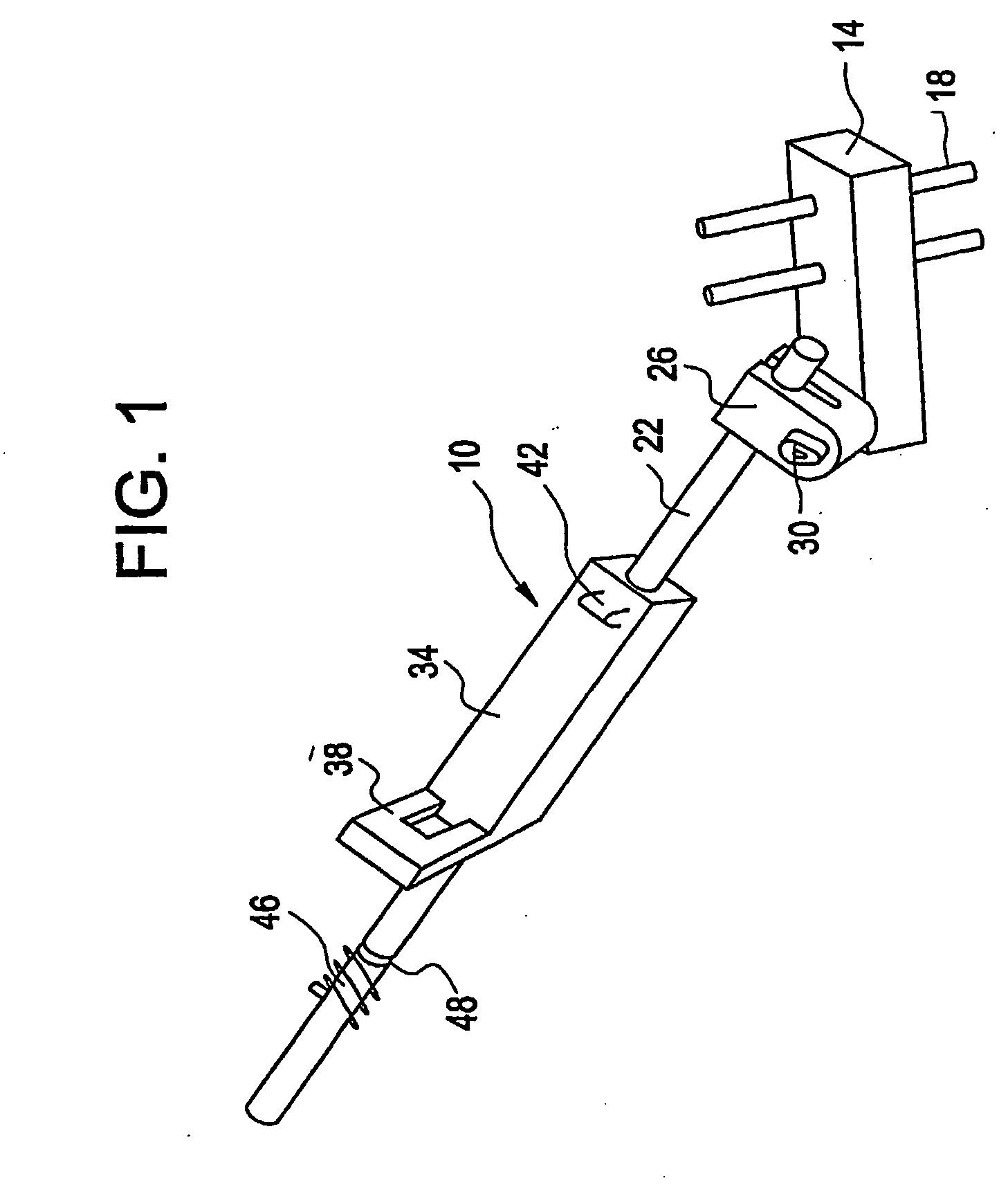
[0020]FIG. 1 is an isometric view of a dual fixator 10 formed according to an embodiment of the present invention. The dual fixator 10 includes a substrate shaped attachment block 14 that carries at least one bone screw 18 threaded therethrough. A U-shaped clamp 26 is connected to an end of the attachment block 14 by a screw or bolt 30. The clamp 26 holds a carrier beam 22 that extends away from the attachment block 14. The carrier beam 22 may be rotatable about the screw 30 such that the carrier beam 22 is repositioned at various points relative to the attachment block 14.

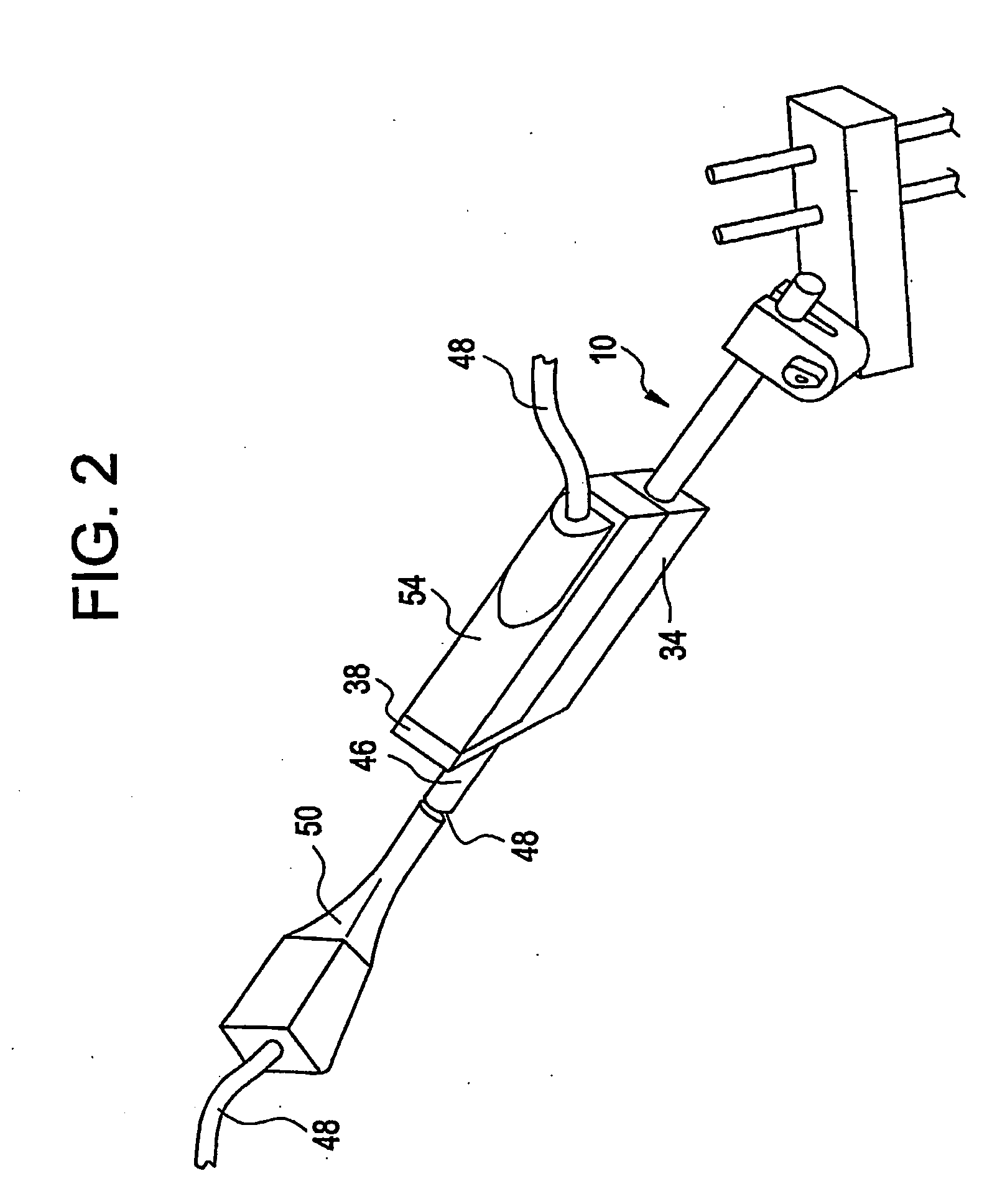
[0021] The carrier beam 22 includes an L-shaped receiver block 34 connected thereto. The receiver block 34 is configured to receive and carry a localizing device such as an electromagnetic receiver (not shown) between a foot 38 and securing ledge 42. Alternatively, the component may be connected to the receiver block 34 by a different means. The carrier beam 22 also includes a cylindrical transmitter post 46 at a...


PUM


Abstract

A system for tracking the position of an instrument relative to an area of interest includes a first fixator configured to carry first and second localizing devices. A second fixator is configured to carry the first localizing device. A third localizing device communicates with the first localizing device and the second localizing device communicates with the first localizing device such that the position of the second localizing device can be determined relative to the position of the third localizing device. The second localizing device is attachable to the instrument and the first localizing device is attachable to the first fixator such that the first localizing device communicates with the second localizing device on the instrument in order that the position of the second localizing device on the instrument can be determined relative to the third localizing device.

Description

RELATED APPLICATIONS [0001] This application claims the benefit of provisional application Ser. No. 60 / 426,314, filed Nov. 14, 2002, the disclosure of which is hereby incorporated in its entirety.BACKGROUND OF THE INVENTION [0002] The present invention relates to a system and method for tracking localizers. More particularly, certain embodiments of the present invention relate to an electromagnetic tracking system and apparatus used for tracking surgical instruments. [0003] During surgical operations, it is beneficial to be able to track the direction and progress of a surgical instrument, such as a drill bit or screw, into a patient's body in order to ensure that the instrument is directed into the appropriate point in the body. Therefore, surgical tracking systems have been developed that are able to monitor and display movement of a surgical instrument relative to an image of the area of the patient's body where surgery is to take place. The area of the patient's body where surge...

Claims


Application Information

Patent Timeline
IPC IPC(8): A61B5/05A61B17/15A61B17/66A61B17/88A61B19/00G01S5/02G01S5/16
CPCA61B6/02A61B6/547A61B17/154A61B17/66A61B17/8866A61B19/5244A61B2019/5251A61B2019/5272A61B2019/5483G01S5/02G01S5/0284G01S5/16A61B2090/3983A61B2034/2072A61B34/20A61B2034/2051A61B6/4441
Inventor KIENZLE, THOMASC III
Owner STRYKER EURO OPERATIONS HLDG LLC
Why Eureka
Try Eureka