
Method and device for clock calibration

a clock and clock technology, applied in the field of clock calibration, can solve the problems of insufficient charge of the lower voltage cell, insufficient clock signal, inability to provide precise clock signals,

Inactive Publication Date: 2006-06-08
FORTUNE SEMICON
View PDF23 Cites 16 Cited by
  • Summary
  • Abstract
  • Description
  • Claims
  • Application Information

AI Technical Summary

Benefits of technology

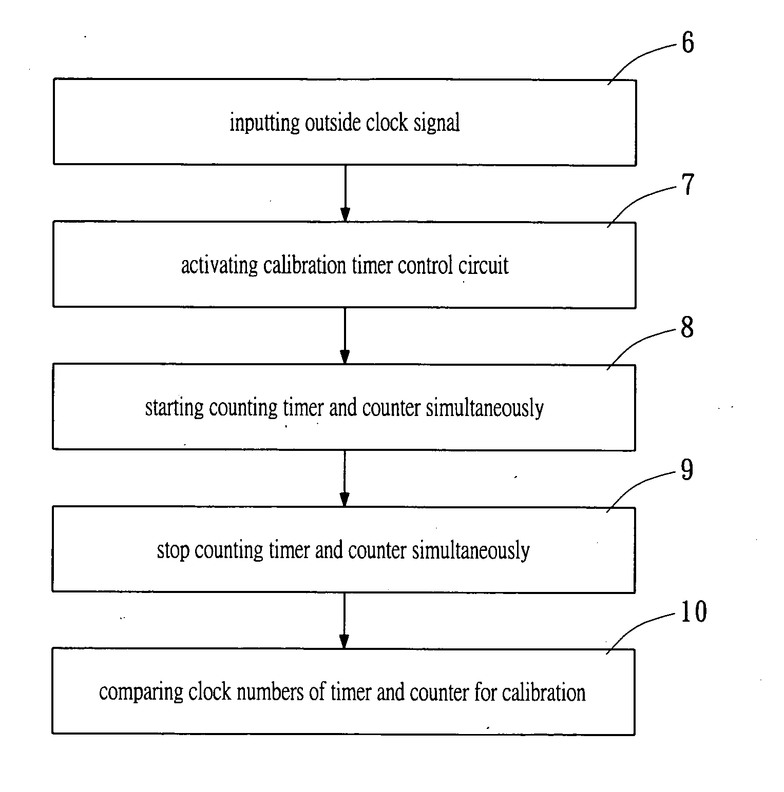
[0006] The present invention provides a method and a device for utilizing an accurate clock signal inputted outside from the power monitoring unit to calibrate an clock generator installed inside the power monitoring unit.

Problems solved by technology

Then, all cells are charged until the cell with higher voltage finishes charging; however, it may happen that the cell with lower voltage is still not charged enough.
However, this kind of clock generator can not provide precise clock signal so that the measured quantity of electricity may not be accurate.
Another method utilizes an exterior clock generator to input more precise clock signal; however, the cost is higher.

Method used


Image

  • Method and device for clock calibration
  • Method and device for clock calibration
  • Method and device for clock calibration

Examples


Embodiment Construction

[0014] Reference will now be made in detail to the preferred embodiments of the present invention, examples of which are illustrated in the accompanying drawings. Wherever possible, the same reference numbers are used in the drawings and the description to refer to the same or like parts.

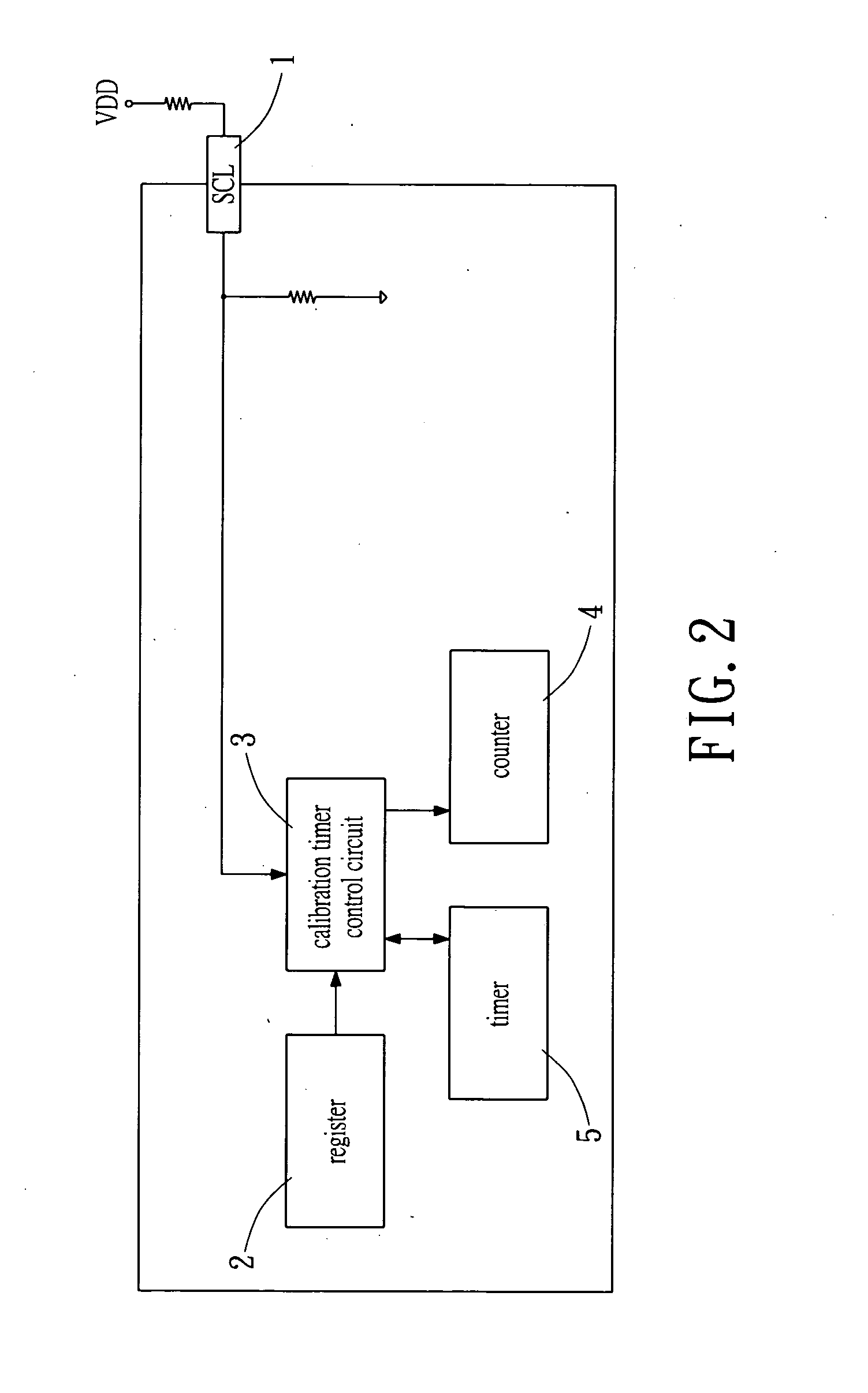
[0015] Referring to FIG. 2, a power monitoring unit 1 of a rechargeable battery includes an input pin 1, a register 2, a calibration timer control circuit 3, a counter 4 and a timer 5. The present invention utilizes an accurate clock signal inputted outside from the power monitoring unit 1 to calibrate an oscillator installed inside the power monitoring unit.

[0016] In the preferred embodiment, the input pin 1 is an inputting terminal of the system management bus (SMBUS SCL) of the power monitoring unit 1 to input the outside clock signal.

[0017] The register 2 is used to generate a start signal for outputting.

[0018] The calibration timer control circuit 3 is connected to the input pin 1 and the r...


PUM


Abstract

A method and a device for calibrating an interior clock generator installed inside a power monitoring unit of a rechargeable battery. The device includes an input pin for inputting an external clock signal from an exterior clock generator installed outside the power monitoring unit. A calibration timer control circuit is connected to the input pin. A register is connected to the calibration timer control circuit for outputting a start signal to activate the calibration timer control circuit. A counter and a timer are controlled by the calibration timer control circuit to be activated simultaneously therewith to count the outside clock signal and an internal clock signal generated from the interior clock generator, respectively. Such that the timer stops counting while the counter stops counting, a first count of the timer is compared to a second count of the counter to calibrate the interior clock generator.

Description

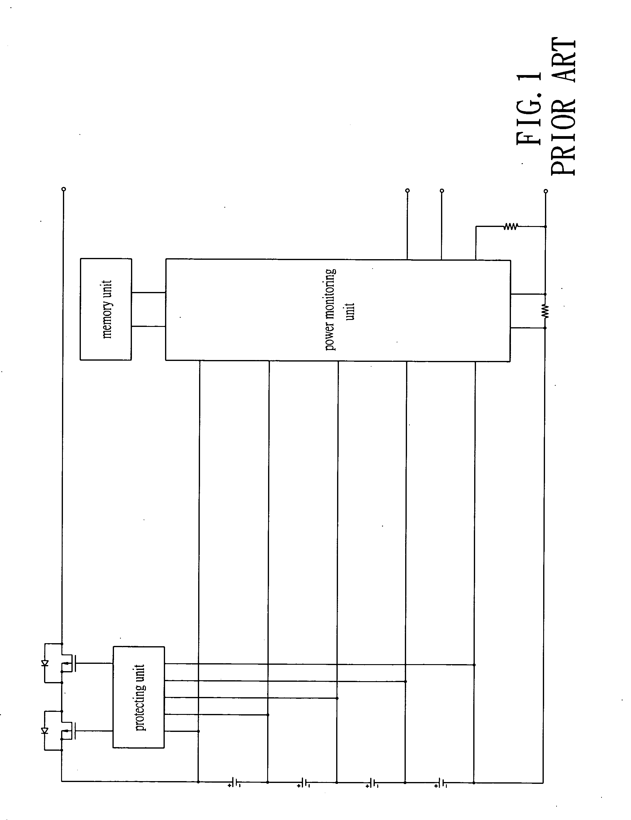
BACKGROUND OF THE INVENTION [0001] The present invention relates in general to a method and device for clock calibration, and more particularly, to a method and device utilizing the inputted external clock signal to calibrate the internal generated clock signals. [0002] Nowadays a computer becomes a daily use in almost every house. The computer can help people to do a lot of things and is playing an important role in the modern life. Some people usually work outside, a laptop computer is more convenient. The laptop computer can utilize an adapter connected to a plug for receiving power. When users take the laptop computer outside, the laptop computer can use a rechargeable battery to provide power. [0003] With reference to FIG. 1, conventional rechargeable battery with a plurality of cells connected in series contains a rechargeable circuit and a protecting and detecting circuit. The protecting and detecting circuit includes a protecting unit and a power monitoring unit. The power m...

Claims


Application Information

Patent Timeline
Patent Type & Authority Applications(United States)
IPC IPC(8): G01R35/00
CPCG01R35/04G04G3/00G06F1/14
Inventor CHEN, YI-CHANGYUAN, KUO-YUANLIAO, YING-CHIENLAI, SHIH-JUNG
Owner FORTUNE SEMICON
Learn More