Method of manufacturing cylindrical bearing member

a technology of cylindrical bearings and bearing parts, which is applied in the direction of sliding contact bearings, other domestic articles, transportation and packaging, etc., can solve the problems of deterioration of lubricating properties, poor oil reserve efficiency, and inability to hold lubricating oil for a long time, so as to improve oil reserving efficiency and efficient formation

Inactive Publication Date: 2006-06-15
TSUBAKIMOTO CHAIN CO
View PDF11 Cites 7 Cited by
  • Summary
  • Abstract
  • Description
  • Claims
  • Application Information

AI Technical Summary

Benefits of technology

[0010] Accordingly, the objects of the present invention are to solve the above-mentioned related art problems and to provide a small cylindrical bearing member, in which maintainability for lubricating oil filled in the blind grooves and oil reserving efficiency can be enhanced by use of seamless cylindrical portion of a cylindrical bearing member and a thin and a relatively thick cylindrical portions can be used, as well as to provide a method of manufacturing a cylindrical bearing member in which blind grooves with blocked-in ends in the longitudinal direction of the cylindrical portion can be efficiently formed on the inner circumferential surfaces thereof.

Problems solved by technology

Accordingly, there were problems that the oil reserve efficiency is bad and when this cylindrical bearing member is used for a long period of time the lubricating properties are deteriorated.
Thus, there is a problem that this butted portion forms a seam in the width direction of the cylindrical portion.
Thus there is a problem that when this cylindrical bearing member is used while inserting a shaft, a pin or the like into this cylindrical bearing member, lubricating oil in the blind grooves leaks on the side of the groove portion formed by the seam and flows out of the ends in the longitudinal direction of the seam for a very short time whereby the lubricating oil cannot be held for a long period of time and the lubricating properties cannot be maintained.
Further, there is a problem that since the cylindrical portion of this cylindrical bearing member is formed by winding a rectangular crude material, manufacturing of a cylindrical portion having a thick wall is difficult and a thick cylindrical portion cannot be formed.
Further, since in the above-mentioned conventional cylindrical bearing member comprising a cylindrical portion having a thick wall, and the blind grooves are formed on the inner circumferential surface of the cylindrical portion by undercutting, broaching or the like, the blind grooves cannot be formed by every one blind groove only, whereby the formation efficiency of the blind grooves are bad, a long time for its processing is needed and the mass production is not suitable, which leads to disadvantageous costs.

Method used


Image

  • Method of manufacturing cylindrical bearing member
  • Method of manufacturing cylindrical bearing member
  • Method of manufacturing cylindrical bearing member

Examples


Embodiment Construction

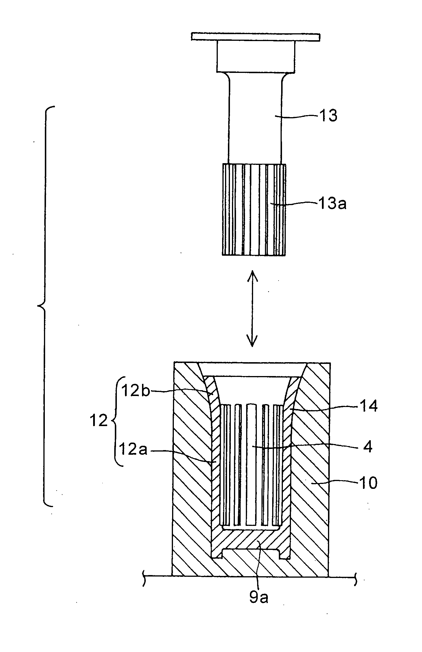
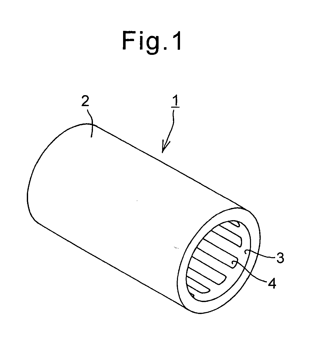
[0028] A cylindrical bearing member made in accordance with the present invention is illustrated in FIGS. 1 and 8. The bearing member 1 is a hollow cylinder 2 having an inner circumferential surface 3. The interior surface 3 is provided with a plurality of blind grooves 4 parallel to the axial direction of the hollow cylindrical portion 2. As shown in FIG. 8, the blind grooves 4 are formed in the central portion 3c of the inner cylindrical surface of the cylindrical portion 2. The opposite ends of the central body portion 3c are spaced from the open ends of the bearing member 1 to form top portion 3a and bottom portion 3b. The blind grooves 4 are confined to the central body portion 3c and terminate in blocked ends 4a and 4b which are spaced inwardly from the open ends of the cylindrical member 1 so that the end portions 3a and 3b of the inner cylindrical surface are provided with a continuous uninterrupted surface. The spacing from the open ends is preferably greater than the thick...


PUM

PropertyMeasurementUnit
axial lengthaaaaaaaaaa
sizeaaaaaaaaaa
lengthaaaaaaaaaa

Abstract

A small-bored cylindrical bearing member which can enhance the maintainability for a lubricating oil therein. The member has blind grooves in a seamless cylindrical central body portion of the interior hollow cylindrical surface of the bearing member. A method of manufacturing the cylindrical bearing member having blind grooves with blocked-in end portions extending in the longitudinal direction of the cylindrical portion and spaced from the ends of the member. The grooves can be easily formed in the central body portion of the inner circumferential cylindrical surface of the central body portion with the blocked-in ends spaced from the opposite ends of the seamless bearing member. The seamless member is first formed with a tapered or flared portion at one open end which is later narrowed into a round cylindrical form. Before narrowing the tapered or flared portion, the blind grooves are formed by a groove punch pushed through the open end into the central body cylindrical portion. After narrowing, the blind grooves have blocked end portions spaced from the opposite ends of the bearing in the longitudinal direction.

Description

TECHNICAL FIELD TO WHICH THE INVENTION PERTAINS [0001] The present invention relates to a cylindrical bearing member having a hollow cylindrical bore in which a plurality of blind grooves, which provide reservoirs for a lubricating oil, were formed in an endless inner circumferential surface of a cylindrical bore in parallel to the axial direction of the cylindrical bore, and a method of manufacturing the bearing member. Particularly, the present invention relates to a bearing member having a cylindrical bore in which these blind grooves were blocked without their ends extending to either of the opposite ends of the cylindrical bore and a method of manufacturing the bearing member in small sizes. BACKGROUND OF THE INVENTION [0002] A cylindrical bearing member, which is used as sliding bearings such as a bearing body for a rotating shaft, a bushing for a chain and the like by inserting a shaft, a pin or the like into the cylindrical bore of the article, has been conventionally well k...

Claims


Application Information

Patent Timeline
Patent Type & Authority Applications(United States)
IPC IPC(8): B21D53/00B21J5/12B21K1/05F16C17/08F16C33/10F16C33/14
CPCF16C33/1065Y10T29/49668Y10T29/49673Y10T29/49636F16C33/04F16C33/10F16C33/64B61L29/226B61L29/28B61L25/02
Inventor MATSUURA, TETSUFUMI
Owner TSUBAKIMOTO CHAIN CO
Why Eureka
Try Eureka