Secondary flow, high pressure turbine module cooling air system for recuperated gas turbine engines

a technology of turbine modules and cooling air systems, which is applied in the direction of machines/engines, stators, mechanical equipment, etc., can solve the problems of reducing engine efficiency, reducing service life, and adversely affecting the relationship between components with different coefficients of thermal expansion

Inactive Publication Date: 2006-06-15
HONEYWELL INT INC
View PDF19 Cites 66 Cited by
  • Summary
  • Abstract
  • Description
  • Claims
  • Application Information

AI Technical Summary

Benefits of technology

[0013] In yet another aspect of the present invention there is provided a method for cooling high pressure turbine module components of a recuperated turbine engine comprising the steps of: providing compressor discharge air by discharging cold compressed air from a compressor; providing a secondary flow cooling air by diverting a portion of the compressor discharge air through an open passage of a strut of a recuperator and turbine support adapter; flowing the secondary flow cooling air from the strut and along an inner flow separator; and cooling the high pressure turbine module components with the secondary flow cooling air.
[0014] The present invention also provides a method for uniform cooling of high pressure turbine module components of a recuperated turbine engine comprising the steps of: providing compressor discharge air by discharging cold compressed air from a compressor, wherein the compressor discharge air flows through an outer flow path to a recuperator and turbine support adapter, the recuperator and turbine support adaptor comprising an annular outer strutted body, the outer strutted body comprising a first outer ring and first inner ring, the first outer ring connected to the first inner ring by a plurality of outer struts, and further comprising at least one outer open passage through the first inner ring, the outer open passage being positioned between two of the outer struts and an open slot at an aft end of the first inner ring of the outer strutted body, an annular inner strutted body, the inner strutted body comprising a second outer ring and a second inner ring, the second outer ring connected to the second inner ring by a plurality of inner struts, at least one of the inner struts further comprising an inner open passage wherein the inner open passage is aligned with the outer open passage, and a thermal spring connecting the first inner ring of the outer strutted body to the second outer ring of the inner strutted body; providing a secondary flow cooling air by diverting a portion of the cold compressed air through the outer open passage and the open slot to the inner open passage of the inner strut of the recuperator and turbine support adapter; flowing the secondary flow cooling air from the inner open passage of the inner struts along an inner flow separator; and cooling the high pressure turbine module components with the secondary flow cooling air.

Problems solved by technology

Under normal operating conditions for gas turbine engines, the engine turbine components are exposed to extreme temperatures, which in time, have the potential to cause distress, reduce engine efficiency and reduce service life.
If the engine is allowed to operate at these extreme temperatures the increased thermal expansion and contraction of these components adversely affects clearances and the relationship between components with different coefficients of thermal expansion.
Therefore, the recuperator discharge air is too hot and does not have the capability to provide adequate cooling to meet the HPT module requirements.
However, the air is diverted through the high temperature side of the engine, resulting in increased temperatures of the cooling air.
This design therefore compromises the effectiveness of the cooling air.
The tortuous internal conduits described in the '406 patent are also susceptible to blockage and seal leakage.

Method used


Image

  • Secondary flow, high pressure turbine module cooling air system for recuperated gas turbine engines
  • Secondary flow, high pressure turbine module cooling air system for recuperated gas turbine engines
  • Secondary flow, high pressure turbine module cooling air system for recuperated gas turbine engines

Examples


Embodiment Construction

[0025] The following detailed description is of the best currently contemplated modes of carrying out the invention. The description is not to be taken in a limiting sense, but is made merely for the purpose of illustrating the general principles of the invention, since the scope of the invention is best defined by the appended claims.

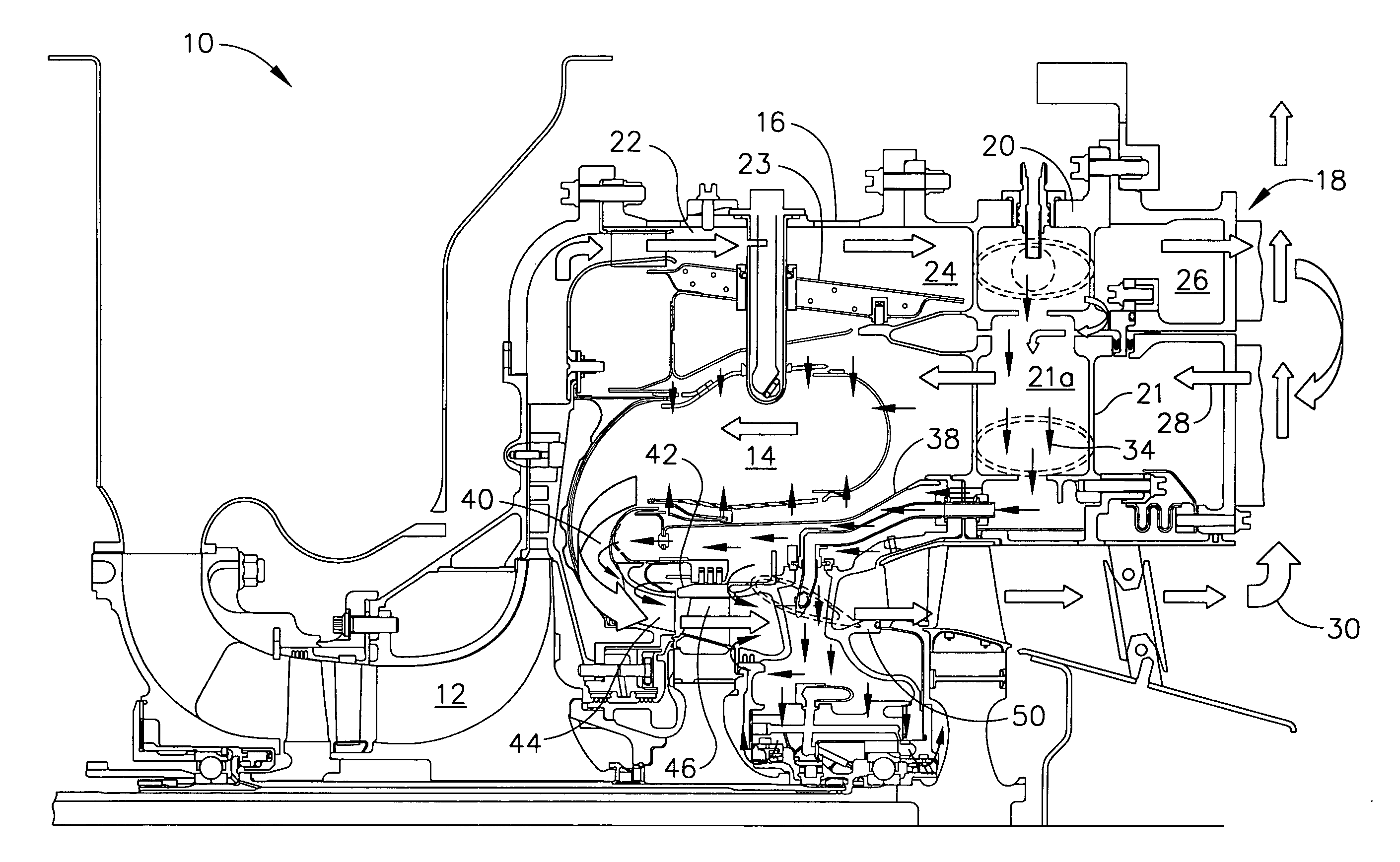
[0026] Broadly, a secondary flow turbine cooling air system for the uniform cooling of turbine module components of a recuperated turbine engine is provided as well as methods for cooling the turbine module components. The secondary flow turbine cooling air system may comprise an outer flow path, and a recuperator and turbine support adapter. The recuperator and turbine support adapter may comprise a plurality of struts in fluid communication with the outer flow path and an inner flow separator. The outer flow path may be defined by a combustor casing of the turbine engine and an outer flow separator. As cold compressed air is discharged from a compre...


PUM


Abstract

A secondary flow, turbine cooling air system for the uniform cooling of high pressure turbine module components such as the turbine shroud, turbine blade tips, turbine nozzle, transion liner, and turbine bearing support housing in a recuperated gas turbine engine is provided. The secondary flow turbine cooling system provides uniform cooling air having a similar pressure and temperature in a recuperated gas turbine engine as the compressor discharge air of a non-recuperated gas turbine engine. A method for uniform cooling of high pressure turbine module components using the secondary flow turbine cooling air system is also provided.

Description

GOVERNMENT RIGHTS [0001] This invention was made with Government support under DAAE07-02-3-0002 awarded by the US Army. The Government has certain rights in this invention.BACKGROUND OF THE INVENTION [0002] This invention relates generally to cooling systems for turbine modules and more specifically to high pressure cooling air systems for turbine modules in recuperated gas turbine engines. [0003] The durability and performance of a gas turbine engine is directly related to the life and efficiency of the high pressure turbine (HPT) module components. Under normal operating conditions for gas turbine engines, the engine turbine components are exposed to extreme temperatures, which in time, have the potential to cause distress, reduce engine efficiency and reduce service life. If the engine is allowed to operate at these extreme temperatures the increased thermal expansion and contraction of these components adversely affects clearances and the relationship between components with dif...

Claims


Application Information

Patent Timeline
Patent Type & Authority Applications(United States)
IPC IPC(8): F02C6/08F02C7/10
CPCF01D9/065F01D25/12F02C7/08F02C7/18
Inventor AYCOCK, LARRY W.BARRETT, JOHN R.BECKER, HOWARD M.DURDEN, MICHAEL J.KIME, ROBERT A.KOCH, BRIAN D.SANDOVAL, ROBERT S.
Owner HONEYWELL INT INC
Why Eureka
Try Eureka