Ladder clamp

a technology of ladders and clamps, applied in the field of ladder clamps, can solve the problems of ladder tilting to one side, general instability of ladders, ladder accidents, etc., and achieve the effect of facilitating the connection of ladder clamps

Inactive Publication Date: 2006-06-15
BRACKEN VINCENT JOSEPH CHRISTOPHER +1
View PDF47 Cites 21 Cited by
  • Summary
  • Abstract
  • Description
  • Claims
  • Application Information

AI Technical Summary

Benefits of technology

[0019] In a further embodiment of the invention there is provided a ladder clamp in which the clamping heads are substantially arcuate in cross-section, the open mouth of each of the clamping heads facing the open mouth of the other clamping head. In this way the ladder clamp may be used to secure the ladder clamp to s

Problems solved by technology

One of the main problems with ladders is their general instability.
One of the most frequent causes of accidents involving ladders is caused by side slippage of the ladder.
This side slippage is often caused by overreaching of an individual when they are up the ladder thereby causing the ladder to tilt to one side.
Typically though, the ladder will be resting against a window sill, parapet wall, gutter or other such type of structure and it is virtually impossible to securely fasten the ladder to any of these structures simply by tying the ladder to the structure.
A problem with this type of clamp is that a user must then tighten both the clamping screw and the pair of hand nuts in order to secure the ladder in position.
This can be a relatively cumbersome and time consuming

Method used


Image

  • Ladder clamp
  • Ladder clamp
  • Ladder clamp

Examples


Embodiment Construction

[0021] The invention will now be more clearly understood from the following description of some embodiments thereof given by way of example only with reference to the accompanying drawings in which:—

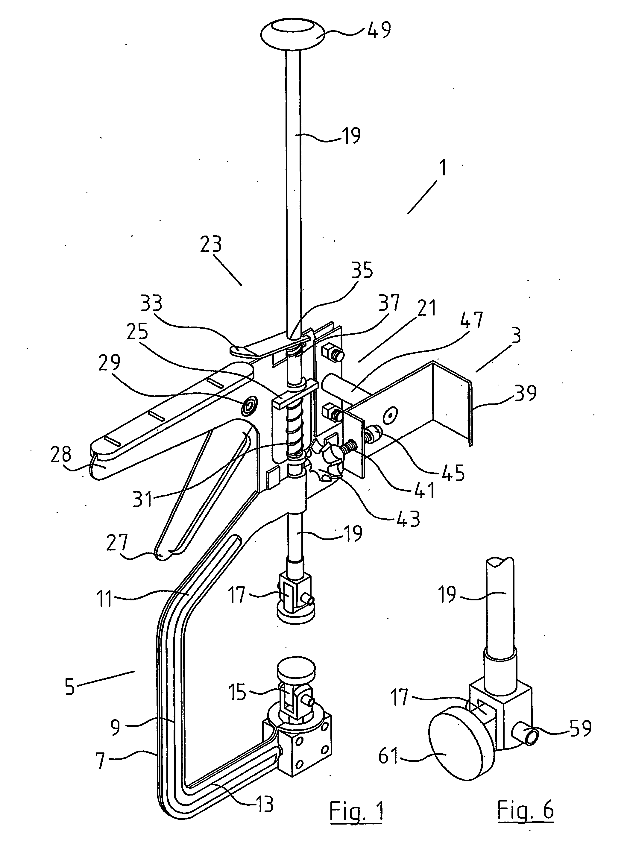
[0022]FIG. 1 is a rear perspective view of a ladder clamp according to the present invention;

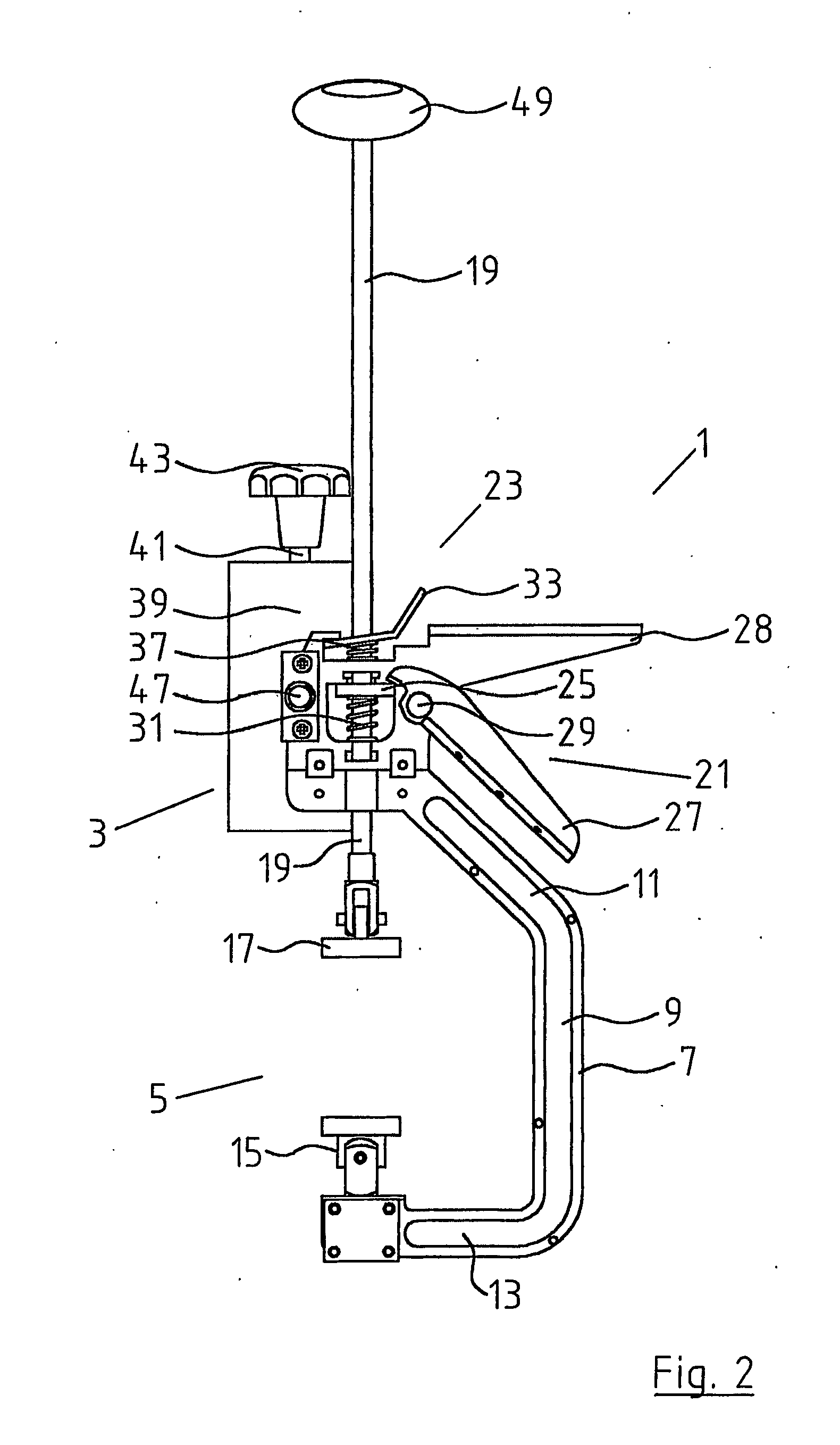
[0023]FIG. 2 is a left hand side view of the ladder clamp shown in FIG. 1;

[0024]FIG. 3 is a right hand side view of the ladder clamp shown in FIG. 1;

[0025]FIG. 4 is a rear perspective view of an alternative construction of ladder clamp according to the invention;

[0026]FIG. 5 is a rear perspective view of another alternative construction of ladder clamp according to the invention;

[0027]FIG. 6 is an enlarged view of the movable clamping head used with the ladder clamp according to the invention;

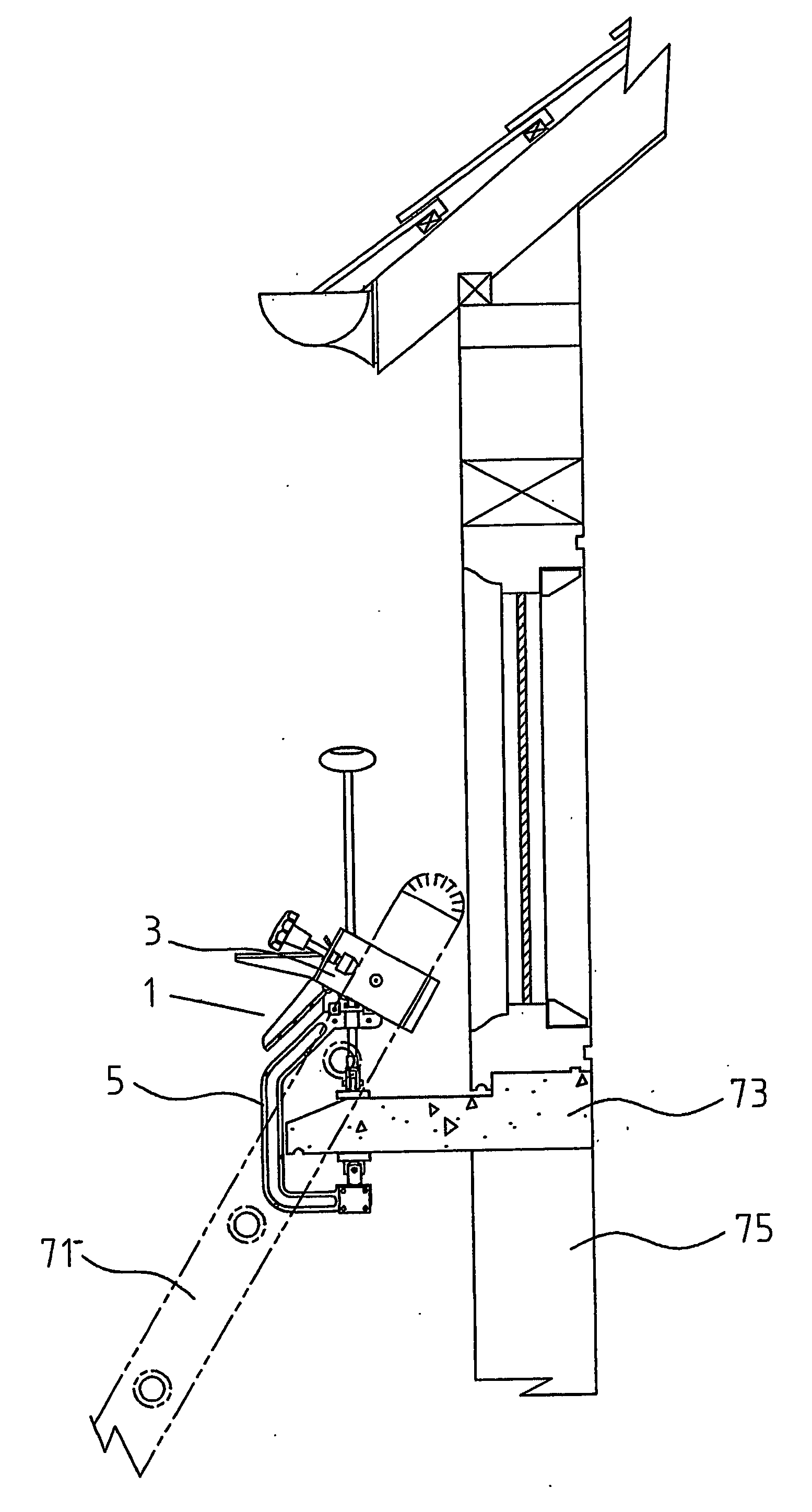
[0028]FIG. 7 is a right hand side view of a ladder clamp according to the invention in use with the ladder clamp secured to a ladder and a window sill, the ladder being shown in ghost; and

[0029]FIG. 8...


PUM


Abstract

A ladder clamp (1) comprises a securing clamp (3) for mounting fast on a ladder and a structure engaging clamp (5) connected to the securing clamp for securing the ladder clamp to a portion of a structure. The structure engaging clamp further comprises a substantially c-shaped bracket (7) and a driving rod (19) slidable within a bore on the c-shaped bracket. A driven ratchet mechanism (21) is located between the driving rod and the c-shaped bracket for urging the driving rod towards a fixed clamping head (15) mounted on the c-shaped bracket and there is additionally provided a quick release locking means (23) to release the driven ratchet mechanism. The ladder clamp may thus be connected and disconnected in a quick and secure manner.

Description

INTRODUCTION [0001] The present invention relates to a ladder clamp comprising a securing clamp for mounting fast on a ladder and a structure engaging clamp connected to the securing clamp for securing the ladder clamp to a portion of a structure. [0002] One of the main problems with ladders is their general instability. One of the most frequent causes of accidents involving ladders is caused by side slippage of the ladder. This side slippage is often caused by overreaching of an individual when they are up the ladder thereby causing the ladder to tilt to one side. It is known, for example, to provide struts and the like to support a ladder on the ground and indeed in many situations it is considered good practice to in some way bind the ladder to the structure against which it is resting. In order to bind the ladder to a structure, a rope or other similar item must be anchored to both the ladder and the structure. Typically though, the ladder will be resting against a window sill, ...

Claims


Application Information

Patent Timeline
IPC IPC(8): E06C7/42E06C1/34E06C7/06E06C7/48
CPCE06C1/34E06C7/48
Inventor BRACKEN, VINCENT JOSEPH CHRISTOPHERMAY, STEPHEN
Owner BRACKEN VINCENT JOSEPH CHRISTOPHER
Why Eureka
Try Eureka