Blood purifying device and method of operating the same

a technology of purifying device and purifying device, which is applied in the direction of filtration separation, multi-stage water/sewage treatment, separation process, etc., can solve the problems of unsatisfactory flow rate accuracy in the removal weight of body fluid, increase the risk of abnormal body fluid balance of patients, and complicated system structure, so as to reduce the error of removal weight and reduce the overall cost, including the cost of the control unit.

Inactive Publication Date: 2006-06-15
ASAHI KASEI MEDICAL CO LTD
View PDF1 Cites 26 Cited by
  • Summary
  • Abstract
  • Description
  • Claims
  • Application Information

AI Technical Summary

Benefits of technology

[0042] Thus, in the blood purifying apparatus and methods of controlling the same in accordance with the invention, the individual reservoir containers (the dialysate reservoir container 9, the replacement fluid reservoir container 10, and the drain reservoir container 8) are weighed by a single weightmeter all at the same time, thereby making it possible to reduce the error in the removal weight of body fluid to the order of 0.2% of the drain fluid weight, as will be described later. This is a significant improvement as compared with the conventional apparatuses of the type whereby each reservoir container is measured individually, where the error can be reduced only to about 2% or so of the drain fluid weight. The error in the feed weight can also be maintained at the same level as that in the conventional apparatuses. Furthermore, since the apparatus of the invention employs only one weightmeter, the overall cost, including that of the control unit, can be significantly reduced.

Problems solved by technology

When there are such large errors, a problem could arise where the blood purifying procedure increases the risk of the body fluid balance of the patient becoming abnormal, rather than providing the intended therapeutic effect.
However, in this blood purifying apparatus, it is necessary to combine conventional dialysis apparatuses when performing a hemodialysis, which leads to unsatisfactory flow rate accuracy in the removal weight of body fluid and to a complicated structure of the system.

Method used


Image

  • Blood purifying device and method of operating the same
  • Blood purifying device and method of operating the same
  • Blood purifying device and method of operating the same

Examples


Embodiment Construction

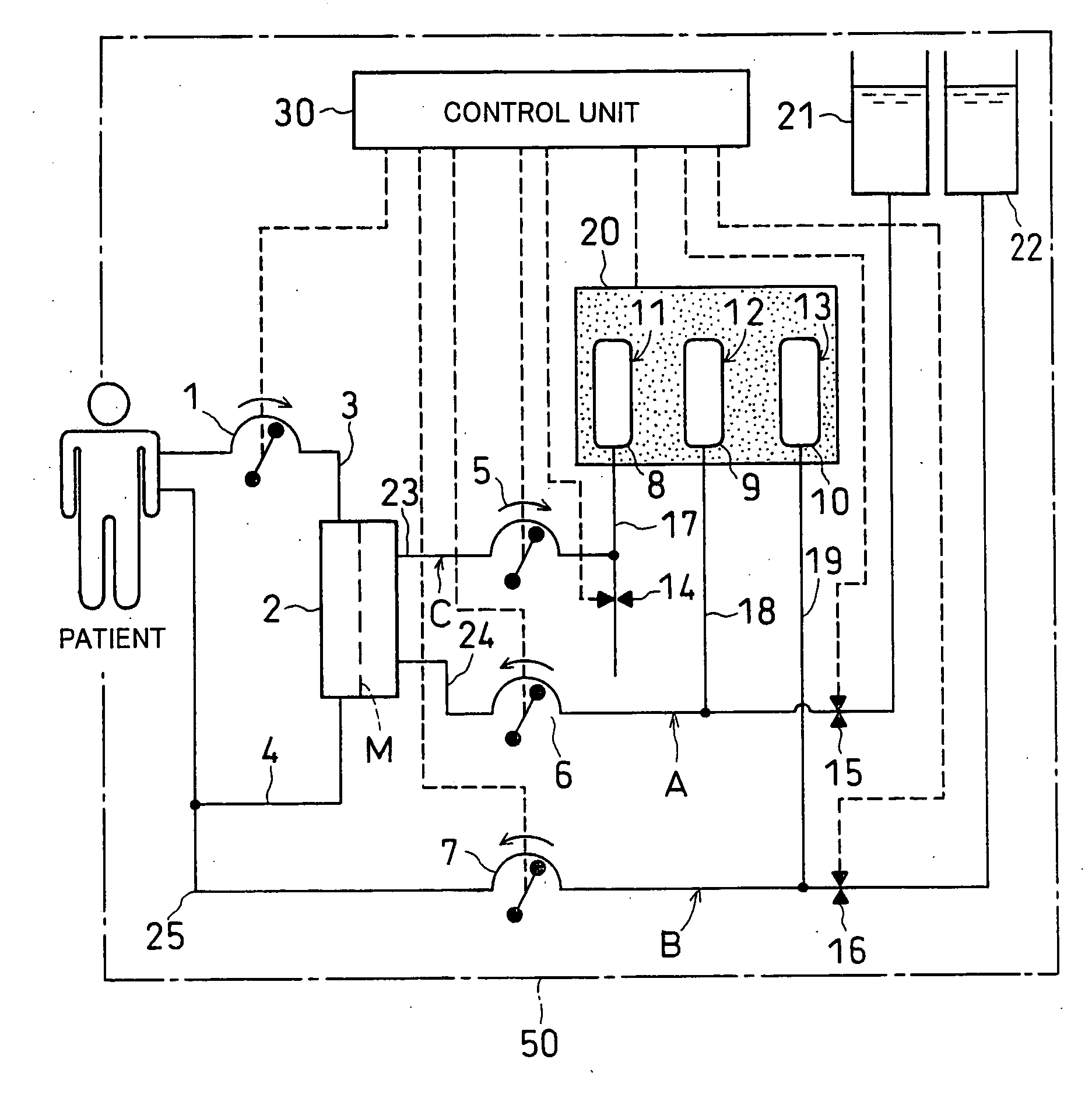
[0046] A blood purifying apparatus of the invention will be hereafter described with reference made to the accompanying drawings. FIG. 1 schematically shows an embodiment of the blood purifying apparatus of the invention. Apparatus 50 is basically the same as the apparatus shown in FIG. 3. Namely, the apparatus 50 is adapted for the continuous hemodiafiltration (CHDF) method combining continuous hemofiltration (CHF) and continuous hemodialysis (CHD). In FIG. 1, constituent members with the same functions as those of the constituent members shown in FIG. 3 are identified by similar reference characters.

[0047] As in the conventional apparatus shown in FIG. 3, the blood purifying apparatus 50 is comprised of a blood drawing line 3 and a blood retransfusing line 4 constituting a blood circulation path; a drain means C for discharging water containing waste products, for example; replacement fluid feed means B connected to the blood retransfusing line 4 for injecting a replacement fluid...


PUM

PropertyMeasurementUnit
flow rateaaaaaaaaaa
flow rateaaaaaaaaaa
flow rateaaaaaaaaaa

Abstract

A blood purifying apparatus particularly suitable for continuous blood purification, and a method of controlling the same whereby the weight of body fluid removed from a patient and a feed weight to the patient can be more accurately controlled. A blood purifying apparatus 50 adapted for the continuous blood purification includes a drain C, a dialysate feed A, and a replacement fluid feed B, which are equipped with transfer pumps 5, 6, 7, respectively, reservoir containers 8, 9, and 10, respectively, that are capable of storing a predetermined volume, and fluid level sensors 11, 12, and 13, respectively. The blood purifying apparatus further includes a single weightmeter 20 capable of measuring the reservoir containers 8, 9, and 10 all at the same time.

Description

FIELD OF THE INVENTION [0001] The present invention relates to a blood purifying apparatus and a method of controlling the apparatus, particularly to a blood purifying apparatus and a method of controlling the apparatus suitable for the generically called continuous blood purification, such as continuous hemofiltration, continuous hemodialysis, and continuous hemodiafiltration. BACKGROUND ART [0002] In renal failure patients, normally urine volumes decrease due to deterioration of renal function, often resulting in overhydration. A treatment is therefore required that would pass the blood of the patient through an extracorporeal circulation so that the condition of their body's water can be as nearly normalized as possible. This process of removing water from the body is referred to as “body fluid removal.” Because the total body fluid variation amount is managed based on the removal weight of body fluid during treatment, the removal weight of body fluid is considered the most impor...

Claims


Application Information

Patent Timeline
Patent Type & Authority Applications(United States)
IPC IPC(8): B01D61/26A61M1/16A61M1/34
CPCA61M1/16A61M2205/3382A61M2205/3393A61M1/3437A61M2205/3386A61M2205/3365A61M2205/3334A61M1/1601A61M2205/50A61M1/1643
Inventor OKAZAKI, SOICHIROU
Owner ASAHI KASEI MEDICAL CO LTD
Why Eureka
Try Eureka