Supercharge Your Innovation With Domain-Expert AI Agents!

Motor with stator formed by assembling divided stator-members into an annular shape, and compressor incorporating the same motor

a stator-member, motor technology, applied in the direction of magnet circuit shape/form/construction, piston pump, magnetic circuit rotating parts, etc., can solve the problems of low motor efficiency, increased current, damage to electrical insulation, etc., and achieves small, efficient, simple structure

Inactive Publication Date: 2006-06-15
PANASONIC CORP
View PDF14 Cites 12 Cited by
  • Summary
  • Abstract
  • Description
  • Claims
  • Application Information

AI Technical Summary

Benefits of technology

"The present invention provides a small, efficient, and high performance motor in a simple structure. The motor includes a stator and a rotor, with the stator being formed by assembling multiple stator members. Each stator member is made by laminating a plurality of core sheets and bonding them with adhesive. The motor structure allows for efficient insulation between the core sheets, resulting in improved motor efficiency. The invention also provides a compressor incorporating this motor."

Problems solved by technology

However, this welding damages electrical insulation at welding spots 64 between the core sheets laminated.
At the damaged spots, eddy current increases, and the motor efficiency lowers.
Therefore, the damages of insulation increases eddy current substantially, which results in lowering the motor efficiency.
In the case of pursuing a highly efficient motor, the punched core-sheets are often annealed in order to remove distortion produced by the punching, because the distortion adversely affects magnetic characteristics.
However, the adhesive does not work at this annealing temperature, and the sheets cannot be properly annealed.
The caulked parts according to this method, however, adversely affects the magnetic characteristics, and lowers the motor efficiency.
This deflection is unfavorable to the motor, in particular, of which stator is formed by assembling a plurality of divided members.

Method used


Image

  • Motor with stator formed by assembling divided stator-members into an annular shape, and compressor incorporating the same motor
  • Motor with stator formed by assembling divided stator-members into an annular shape, and compressor incorporating the same motor
  • Motor with stator formed by assembling divided stator-members into an annular shape, and compressor incorporating the same motor

Examples


first exemplary embodiment

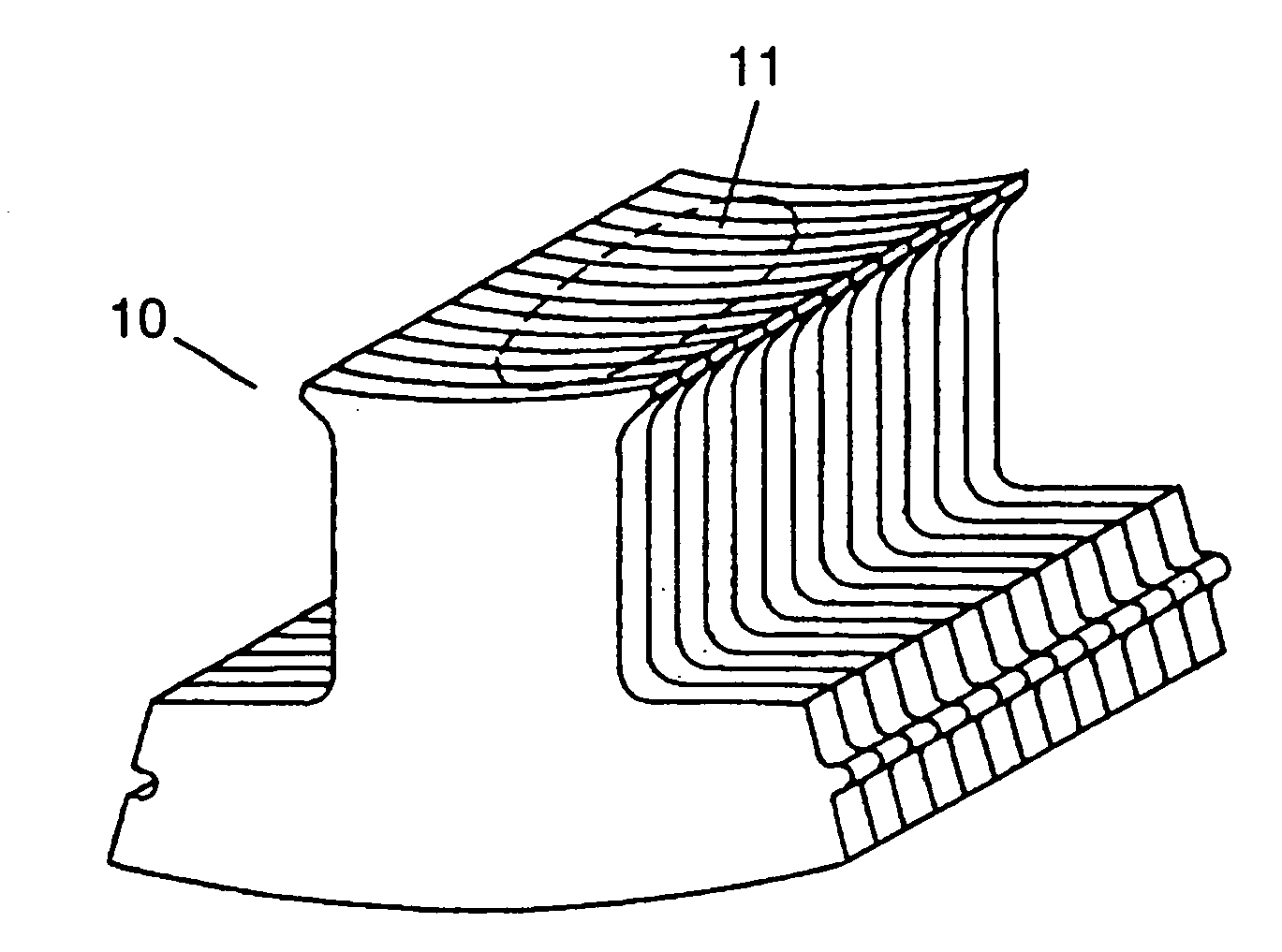
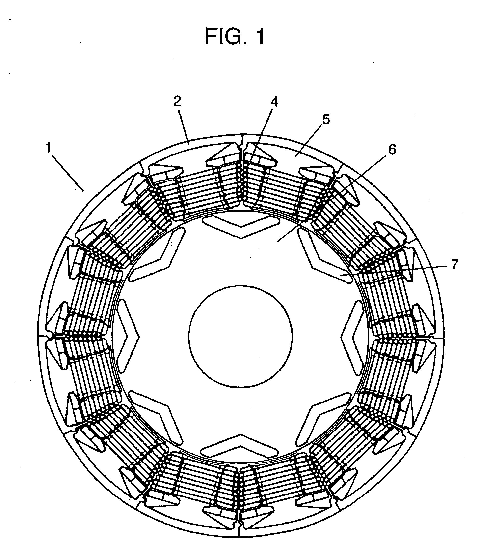
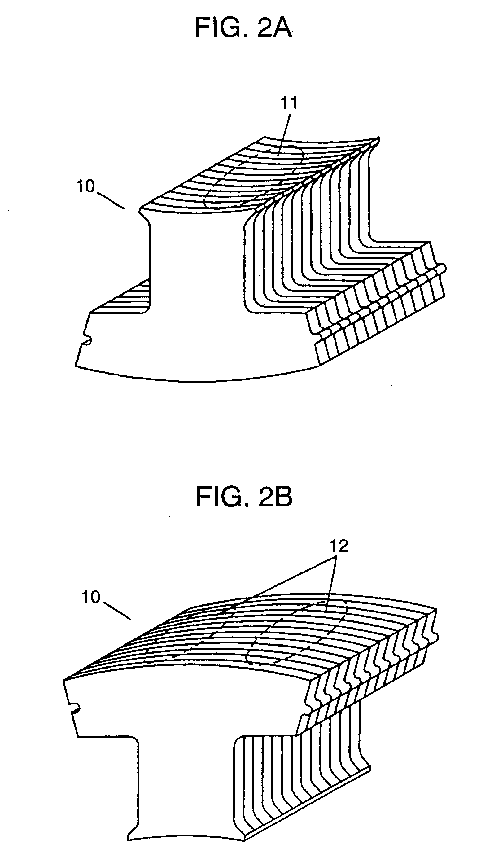
[0025]FIG. 1 is a front view of a motor employing a stator having concentrated windings in accordance with the first exemplary embodiment of the present invention. FIG. 2A and FIG. 2B are perspective views of a stator tooth of the motor shown in FIG. 1.

[0026] In FIG. 1, stator 1 is formed by assembling 12 pieces of divided stator members 2 into an annular shape. Each one of divided stator members 2 has a tooth, and has been wound with windings 4 in a concentrated manner via insulator 5. Rotor 6 has eight pieces of permanent magnets 7 within a core, and faces stator 1 via an annular space. Stator 1 and rotor 6 form a motor having interior magnets.

[0027] This first embodiment refers to the motor with interior magnets; however, the present invention is applicable to a motor with surface magnets, or a switched reluctance motor. In the motor with surface magnets, permanent magnets are disposed on a surface of a rotor core, and the switched reluctance motor uses a stator having concentr...

second exemplary embodiment

[0030]FIG. 3A and FIG. 3B are perspective view of a stator tooth of a motor in accordance with the second exemplary embodiment of the present invention. Stator tooth 20 is formed by laminating a plurality of core sheets made of electromagnetic steel plate. At least parts of end faces along the laminating direction of the core sheets are bonded with adhesive. To be more specific, adhesive is infiltrated into the end faces, of the core sheets laminated, along inner rim 21 of stator tooth 20, so that the core sheets are fixed to each other. As in the first embodiment, instant adhesive of cyanoacrylate system is used, and this adhesive has a low viscosity of ca. not more than 100 mPa·S.

[0031] In the core sheets laminated, parts of a tooth except a section (inner rim of the stator) facing a rotor are welded for fixing the core sheets. This is different from the first embodiment. To be more specific, parts of outer rim 22 (back face of the tooth) are welded, i.e., outer rim 22 does not f...

third exemplary embodiment

[0035] According to a method of integrating divided stator members into an annular shape, connecting sections on the outer rim of the divided members adjacent to each other are welded. In this case, a part of the adhesive evaporates into gas, which interferes with the welding. As a result, the annular stator invites weakness of strength and inaccuracy of precision.

[0036] A measure overcoming this problem is described here with reference to FIG. 5, which is a plan view of stator core-sheet of a motor in accordance with the third embodiment. In FIG. 5, core-sheet 30 includes bonding section 31, welding section 32, and area 33 between bonding section 31 and welding section 32. In bonding section 31, adhesive is infiltrated for bonding a plurality of the core sheets laminated, so that a divided stator member is constructed. At welding section 32, stator teeth adjacent to each other are welded into an annular shape for linking the divided stator-members adjacent to each other. Area 33 i...


PUM


Abstract

A motor includes a stator formed by assembling plural divided-stator-members—each one of the members having a tooth—into an annular shape, and a rotor facing the stator. The divided stator members are formed by laminating plural core sheets and bonding at least parts of end faces along the laminating direction of the core sheets. This structure allows forming a lamination of the core sheets without welding, which avoids damaging electrical insulation between each core sheet. Eddy current thus does not increase at an inner rim of the stator, where magnetic flux intensely changes. The motor efficiency is, therefore, not adversely affected. As a result, a small, efficient and high performance motor in a simple structure is obtainable. A compressor employing the same motor and enjoying the advantages of the motor is also obtainable.

Description

TECHNICAL FIELD [0001] The present invention relates to a motor or an electric generator including a stator formed by assembling divided stator-members into an annular shape, and it relates to an efficient and a high performance compressor incorporating the same motor. BACKGROUND ART [0002] A stator having concentrated windings has been widely used in motors or electric generators. In the concentrated-winding stator, one-phase winding is wound on each tooth of the stator. This stator has an advantage that a height of the winding (winding-end section) can be lowered, so that the motor can be downsized. The concentrated winding stator has a small value of a wire-wound resistor, so that a small copper loss generated by a wire-wound current and a wire-wound resistor is expected. The motor thus can work efficiently. Further, normal winding on a slot section, which can accommodate the winding, increases a space factor of the winding in the stator. The wire-wound resistor value can be thus...

Claims


Application Information

Patent Timeline
Patent Type & Authority Applications(United States)
IPC IPC(8): H02K1/06H02K1/28F04B39/00F04B35/04F04C29/00H02K1/14H02K1/18H02K3/46H02K15/02
CPCF04B35/04F04C29/0085H02K1/148H02K15/022
Inventor NISHIYAMA, NORIYOSHIIKKAI, YASUFUMIOKAZAKI, SEIJI
Owner PANASONIC CORP
Features
  • R&D
  • Intellectual Property
  • Life Sciences
  • Materials
  • Tech Scout
  • Unparalleled Data Quality
  • Higher Quality Content
  • 60% Fewer Hallucinations
Learn More