Method for a changing safety signaling system

a safety signaling and signaling system technology, applied in the direction of signalling/lighting devices, vehicle components, optical signalling, etc., can solve the problems of substantial risks associated with driving automobiles and other vehicles at relatively high speed under hazardous weather conditions, limited light on the front of a vehicle, etc., to increase or decrease the flashing rate, increase or decrease the effect of the flashing ra

Inactive Publication Date: 2006-06-15
SONG WON MOO
View PDF55 Cites 115 Cited by
  • Summary
  • Abstract
  • Description
  • Claims
  • Application Information

AI Technical Summary

Benefits of technology

[0044] In one aspect, the present invention relates to an improved method of increasing the visibility of a vehicle that is in fog or other diminished visibility situation such as a fog, rain, dust storm. In one embodiment, the basic element of the invention is flashing the vehicle's lights. In one embodiment, the flashing indicator is placed adjacent a non-flashing indicator. In an alternative embodiment, the flashing indicator is placed in a location that is non-adjacent the non-flashing indicator. In one embodiment, the flashing is performed with a particular color or set of colors.
[0062] Another object of the present invention relates to the use of audio cues including the vehicle's horn and / or sound system to supplement the use of flashing lights to increase a second vehicle's awareness of the first vehicle.

Problems solved by technology

Lights on the front of a vehicle are generally limited to headlights, marker or running lights, and turn signal lights.
One problem exists when a following vehicle operator does not know whether the preceding operators of vehicles are using the vehicle's accelerator, or are coasting wherein the operator is using neither the accelerator nor brake.
An additional problem exists in that a following vehicle operator does not know how hard the preceding operators of vehicles are applying the brakes.
Further, there are substantial risks associated with driving automobiles and other vehicles at relatively high rates of speed under hazardous weather conditions such as fog.
Another problem exists wherein observers and operators of other vehicles who are positioned in front of a vehicle do not know whether the operator of the vehicle has engaged its brake system.
Sometimes it is difficult to judge whether the driver of an approaching vehicle intends to continue through a yellow semaphore light.
Another problem exists when a vehicle operator of a following vehicle does not know whether the operators of preceding vehicles are using the vehicle's accelerator, or are coasting wherein the operator is using neither the accelerator nor brake.
However, such a brake light does not communicate the state of the acceleration pedal of a vehicle.
Placement of an indicator solely in the front windshield of a vehicle would not be effective when a moving vehicle is observed from the side.
However, there is no disclosure of connecting these green lights to the accelerator of the vehicle.
Although the lights are mounted on the front of a vehicle, the lights are located at the bottom of the front bumper rather than being “high mounted” and do not communicate the state of the accelerator pedal.
However, there is no teaching of a forwardly visible or topward facing indicator.
There is no teaching to mount such a device in a forward facing position.
However, there are instances where the lead vehicle must rapidly reduce its speed.
If the operator of the trailing vehicle fails to concomitantly reduce its speed a collision can occur between the trailing vehicle and the leading vehicle.
If the operator of the trailing vehicle is distracted by, for example, adjusting the radio or dialing on a cell phone, the trailing vehicle may not concomitantly reduce its speed, resulting in a collision event with the lead vehicle.

Method used


Image

  • Method for a changing safety signaling system
  • Method for a changing safety signaling system
  • Method for a changing safety signaling system

Examples


Embodiment Construction

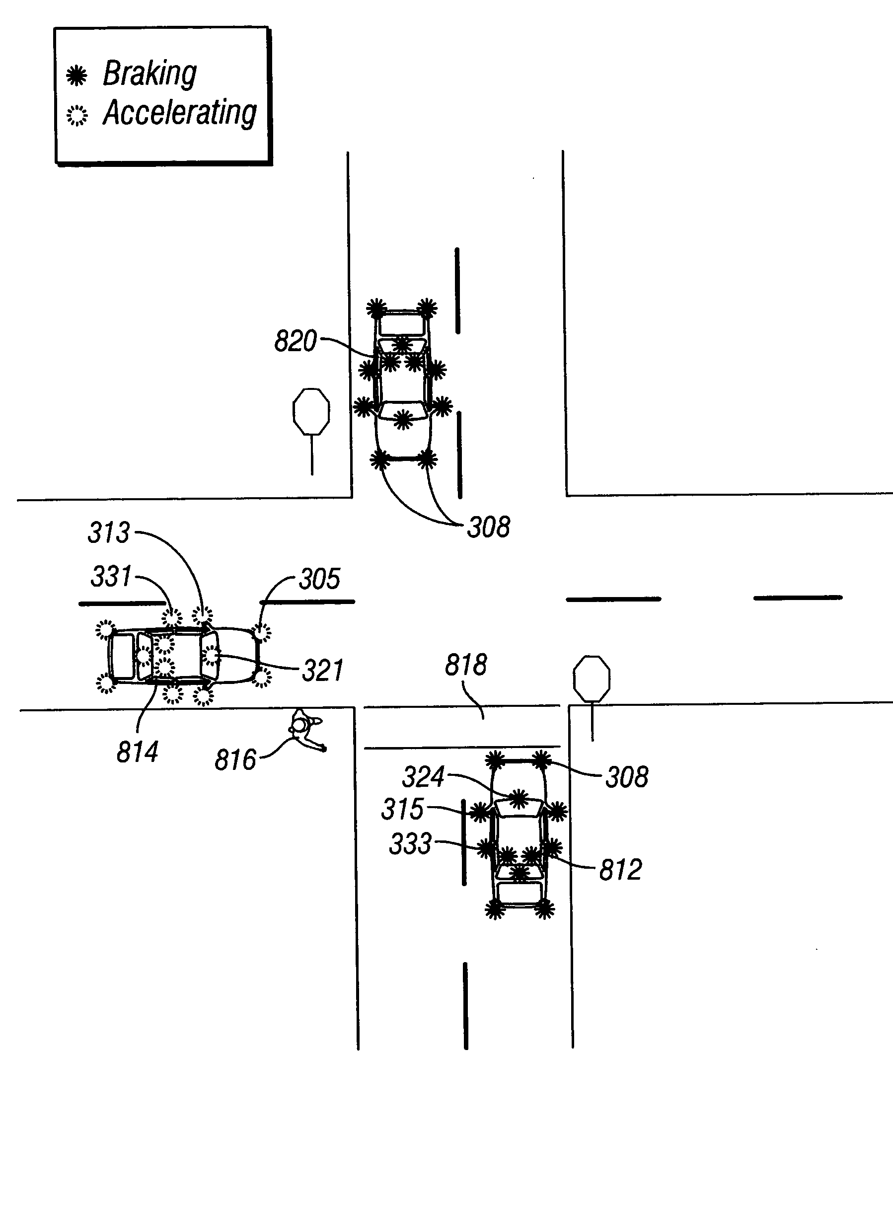
[0189] While the invention is described below with respect to one or more preferred embodiments, other embodiments are possible. The concepts disclosed herein apply equally to other systems for externally indicating acceleration, deceleration and braking of an automobile or other vehicle through detecting the use of a vehicle's brakes and accelerator. Further, in one aspect, the invention is directed towards improved turn indicators. The instant invention can be used with any vehicle that can use a signaling system including, but not limited to any motor vehicle, automobile, mass transportation vehicle, truck, tractor trailer, bus, school bus, commercial vehicle, commercial equipment, industrial equipment, military vehicle, snowmobile, watercraft including jet skis and boats, submarines, and ships, scooter, motorcycle, minibike, bicycle, go-cart, moped, unmanned vehicle, toy car, toy ship, or toy aircraft and aircraft. The instant invention can be used with any vehicle that can use ...


PUM


Abstract

The present invention provides a method for a changing safety signaling system. The safety signaling system can change as a result of changing driving conditions that stem from changes in the weather or changes in vehicle velocity. As a vehicle brakes, coasts, turns, or accelerates, front-facing, side-facing, top-facing, and / or rear facing indicators can communicate vehicular acceleration, coasting, and braking to a pedestrian or other vehicles. A distance sensor can be used to trigger a signal to alert a second vehicle that the first vehicle is braking hard and slowing fast or can be used to warn the operator of the first car that a collision may be imminent and can be used to warn the operator of a second car that measures can be taken to avoid a collision or minimize damage from a collision. The instant invention can be utilized by either a first car or a second car.

Description

CROSS REFERENCE TO RELATED APPLICATION [0001] This application is a continuation-in-part of U.S. application Ser. No. 10 / 999,443 entitled “Improved Vehicle Accelerator and Brake Indicators” and filed on Nov. 29, 2004, and a continuation-in-part of U.S. application Ser. No. 11 / 057,970, entitled “System for Improving the Visibility of a Vehicle During Reduced Visibility Conditions”, filed on Feb. 15, 2005.BACKGROUND [0002] 1. Technical Field [0003] This invention relates generally to the field of safety signal indicator systems installed on a vehicle, and more particularly to a method for changing the safety signaling system based on changing driving conditions. [0004] 2. Background of the Invention [0005] Operating lights are used on all types of vehicles including, but not limited to, aircraft, cars, motorcycles, trucks, trains, bicycles, and toy vehicles. Brake lights of currently produced vehicles are typically red and are usually found only on the rear of a vehicle. Many vehicles...

Claims


Application Information

Patent Timeline
Patent Type & Authority Applications(United States)
IPC IPC(8): B60Q1/22B60Q1/26B60Q1/52
CPCB60Q1/38B60Q1/44B60Q1/442B60Q1/46B60Q1/381
Inventor SONG, WON MOO
Owner SONG WON MOO
Why Eureka
Try Eureka