
Indefinite materials

Inactive Publication Date: 2006-06-15
RGT UNIV OF CALIFORNIA
View PDF12 Cites 141 Cited by
  • Summary
  • Abstract
  • Description
  • Claims
  • Application Information

AI Technical Summary

Problems solved by technology

While providing many interesting and useful capabilities, however, the “perfect lens” and other proposed negative permeability / permittivity materials have some limitations for particular applications.
For example, researchers have suggested that while the perfect lens is fairly robust in the far field (propagating) range, the parameter range for which the “perfect lens” can focus near fields is quite limited.
The limitations of known negative permittivity and permeability materials limit their suitability for many applications, such as spatial filters.

Method used


Image

  • Indefinite materials
  • Indefinite materials
  • Indefinite materials

Examples


Embodiment Construction

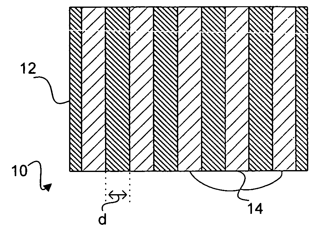
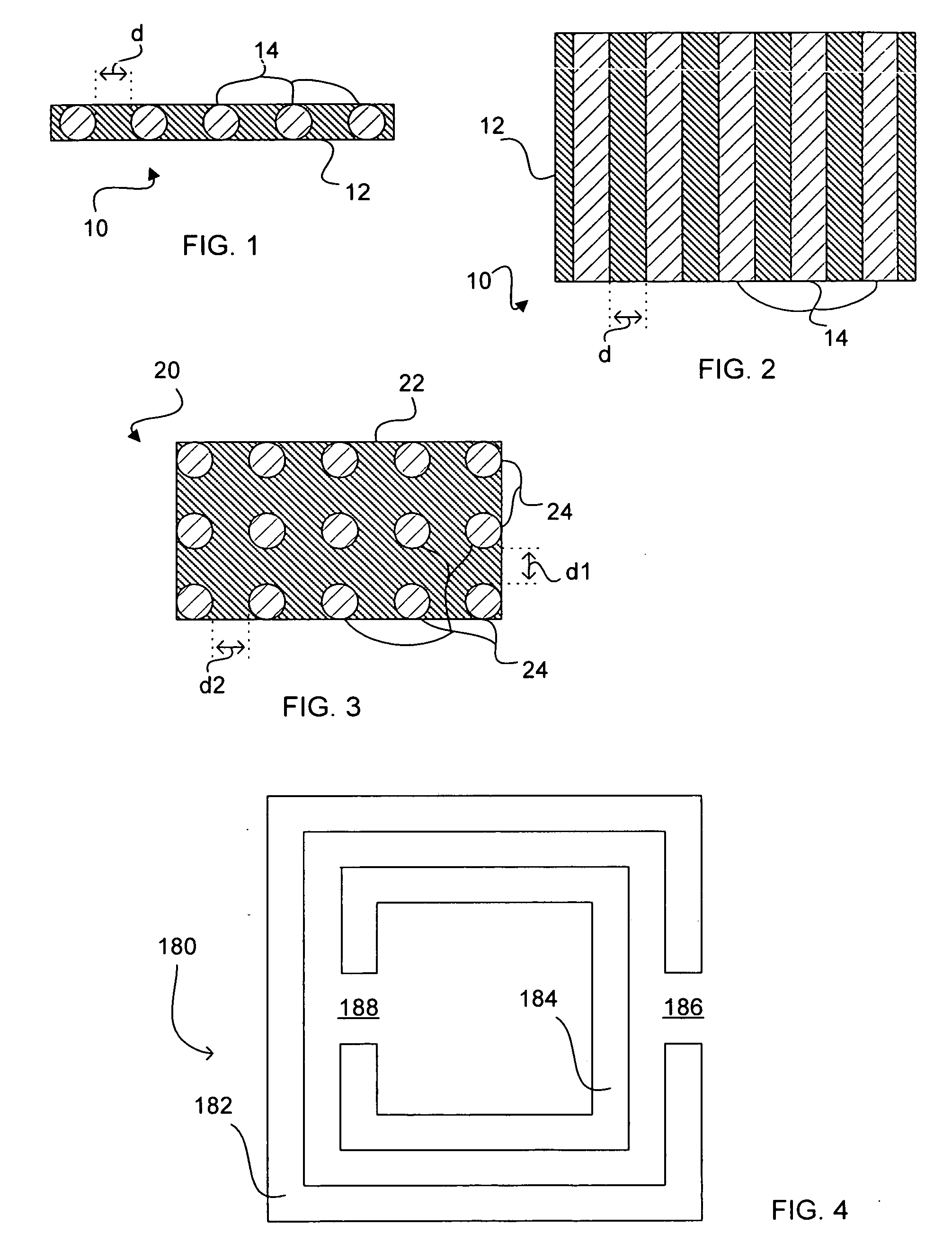
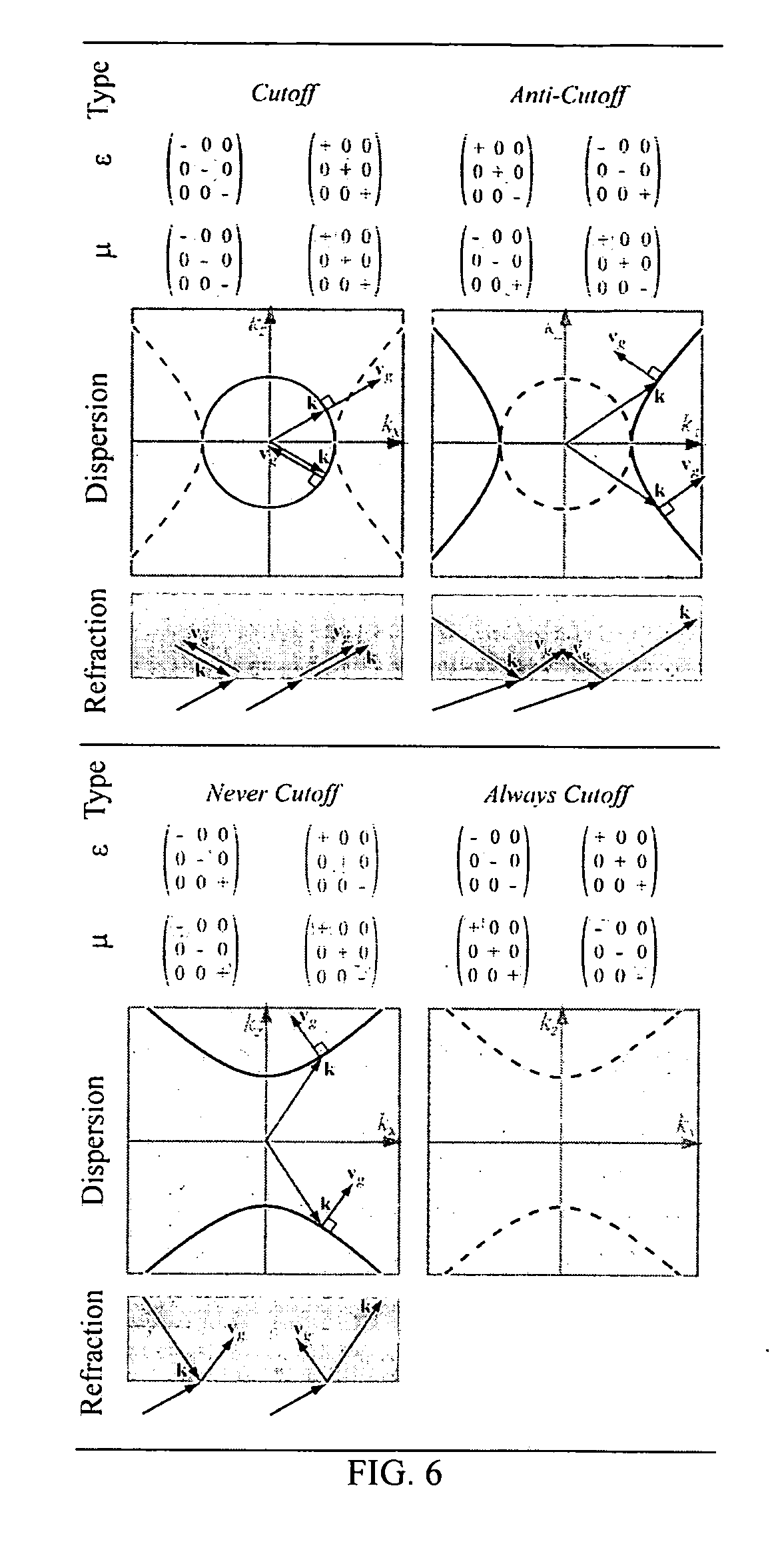
[0022] Indefinite media have unique wave propagation characteristics, but do not generally match well to free-space. Therefore, a finite section of an indefinite medium will generally present a large reflection coefficient to electromagnetic waves incident from free space. It has been discovered, however, that by combining certain classes of indefinite media together into bilayers, nearly matched compensated structures can be created that allow electromagnetic waves to interact with the indefinite media. Compensating multi-layer materials of the invention thus have many advantages and benefits, and will prove of great utility in many applications.

[0023] One exemplary application is that of spatial filtering. An exemplary spatial filter of the invention can perform similar functions as traditional lens-based spatial filters, but with important advantages. For example, the spatial filter band can be placed beyond the free-space cutoff so that the processing of near-fields is possible...


PUM


Abstract

A compensating multi layer material includes two compensating layers adjacent to one another. A multi-layer embodiment of the invention produces subwavelength near-field focusing, but mitigates the thickness and loss limitations of the isotropic “perfect lens”. An antenna substrate comprises an indefinite material.

Description

TECHNICAL FIELD [0001] The present invention is related to materials useful for evidencing particular wave propagation behavior, including indefinite materials that are characterized by permittitvity and permeability of opposite signs. BACKGROUND ART [0002] The behavior of electromagnetic radiation is altered when it interacts with charged particles. Whether these charged particles are free, as in plasmas, nearly free, as in conducting media, or restricted, as in insulating or semi conducting media—the interaction between an electromagnetic field and charged particles will result in a change in one or more of the properties of the electromagnetic radiation. Because of this interaction, media and devices can be produced that generate, detect, amplify, transmit, reflect, steer, or otherwise control electromagnetic radiation for specific purposes. [0003] The behavior of electromagnetic radiation interacting with a material can be predicted by knowledge of the material's electromagnetic...

Claims


Application Information

Patent Timeline
IPC IPC(8): G01S13/08H01Q15/02H01Q15/08H01Q19/06
CPCH01Q15/02H01Q19/062H01Q15/08
Inventor SMITH, DAVID R.SCHURIG, DAVID
Owner RGT UNIV OF CALIFORNIA
Learn More