Antenna systems for passive RFID tags

a technology of passive rfid and antenna system, which is applied in the direction of resonant antenna, burglar alarm mechanical actuation, instruments, etc., can solve the problems of inacceptable performance sensitivity, and achieve the effect of facilitating impedance matching

Active Publication Date: 2009-02-19
FIBER MOUNTAIN INC
View PDF65 Cites 27 Cited by
  • Summary
  • Abstract
  • Description
  • Claims
  • Application Information

AI Technical Summary

Benefits of technology

[0008]An aspect of the invention is an antenna system for a radio-frequency identification (RFID) tag that includes an integrated circuit (IC). The system includes an antenna substrate having a proximal end arranged adjacent the IC, and a distal end. The system also includes a first serpentine antenna element formed on the antenna substrate and having a proximal end electrically connected to the IC. A second antenna element runs in the same direction from the IC as the first serpentine antenna element and has a proximal end c...

Problems solved by technology

Antennas currently used for passive RFID tags typically have one or more unsuitable characteristics, such as being too large, the antenna arms extend away from each other, an...

Method used


Image

  • Antenna systems for passive RFID tags
  • Antenna systems for passive RFID tags
  • Antenna systems for passive RFID tags

Examples


antenna example embodiments

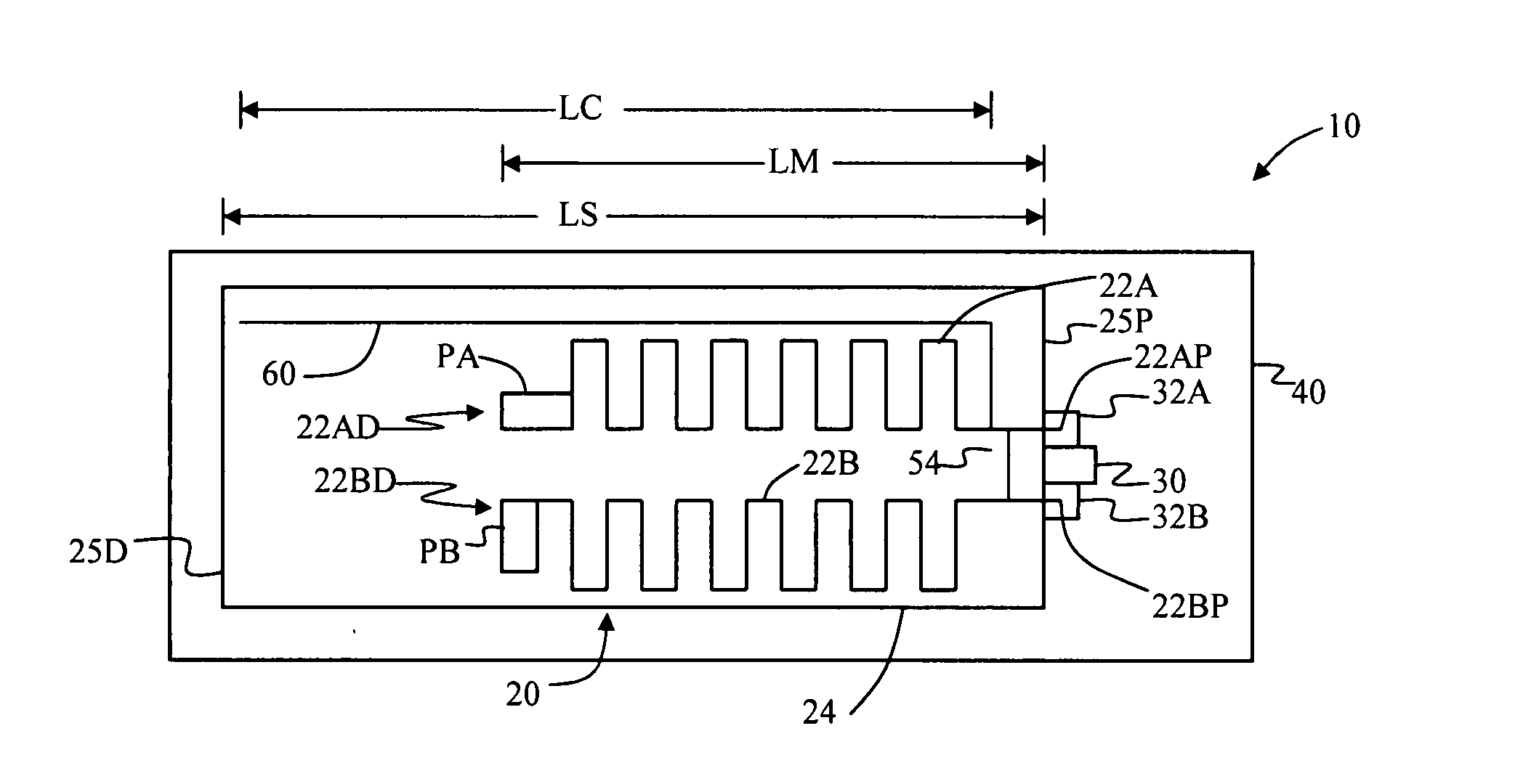
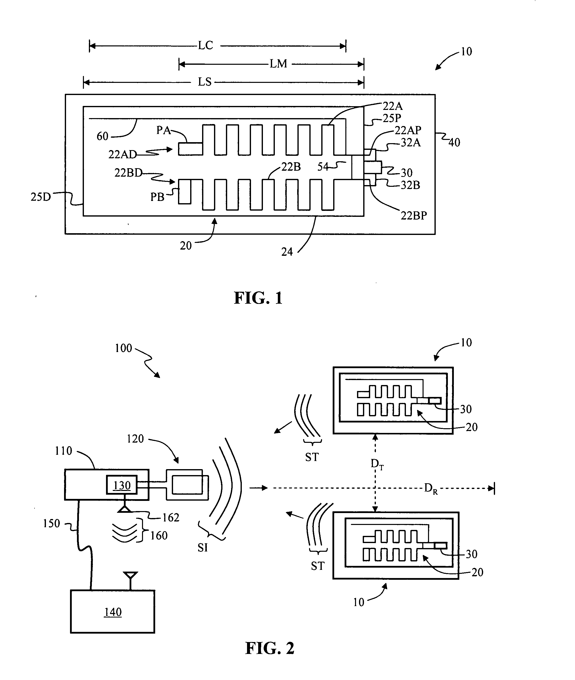
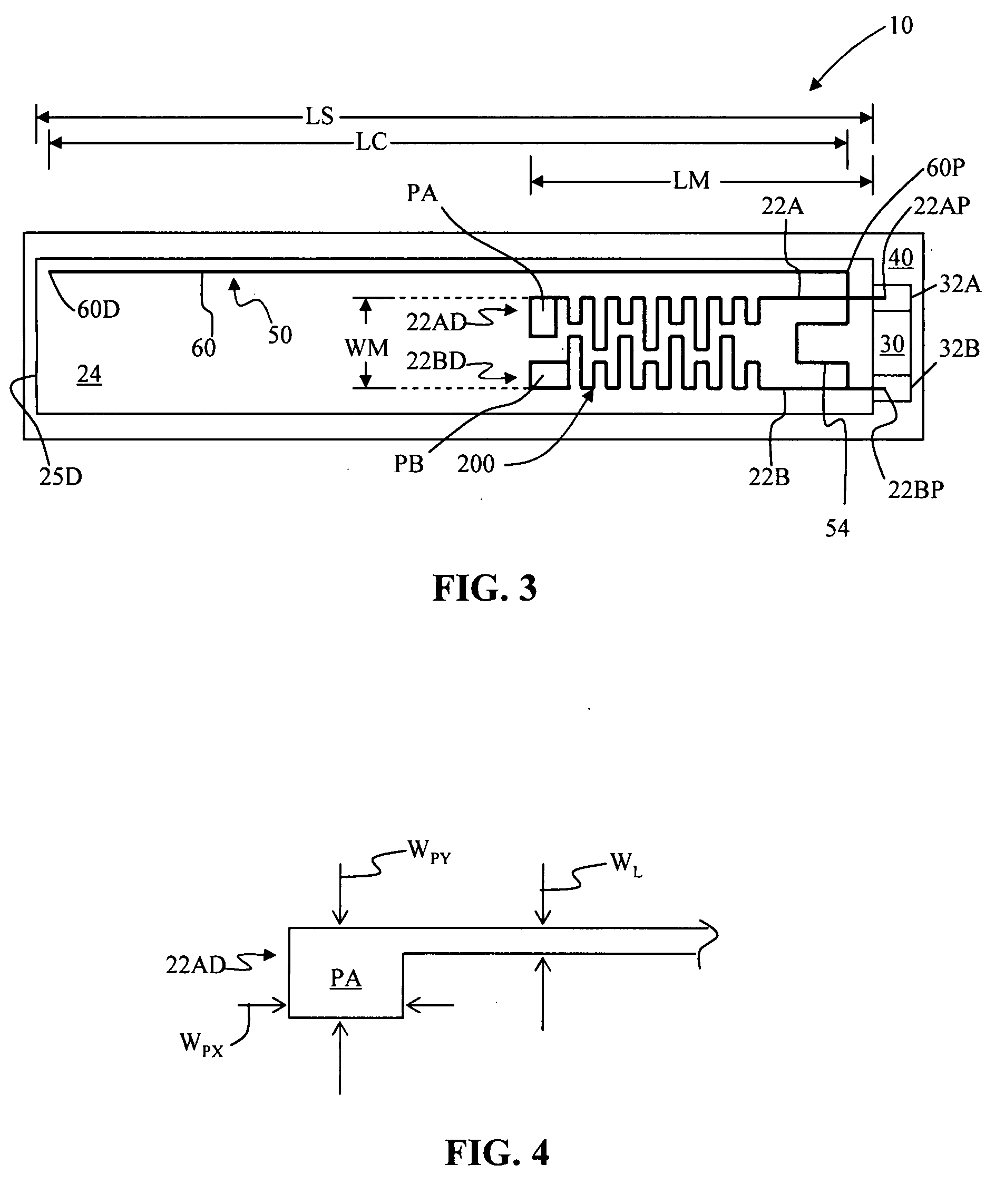
[0037]FIG. 3 is a schematic plan view of an example embodiment of antenna 20 according to the present invention as used in a passive RFID tag 10 according to the present invention. Generally, antenna 20 includes at least one serpentine antenna element, and the example embodiment of FIG. 3 includes two serpentine antenna elements 22A and 22B. In an example embodiment, serpentine antenna elements 22A and 22B are in the form of antenna traces (e.g., metallic conducting lines) that run in the same direction (and in this sense are “parallel”), namely in the long direction of antenna substrate 24 and away from the corresponding antenna feed points 32A and 32B. In an example embodiment, antenna elements 22A and 22B are formed from a conducting metallic material such as conductive ink, metal, etc., using standard techniques.

[0038]In an example embodiment, antenna elements 22A and 22B respectively include flat contact areas (“antenna pads”) PA and PB at their respective distal ends 22AD and ...


PUM


Abstract

Antenna systems for passive radio-frequency identification (RFID) tags. The antenna systems have a very small form factor with good power harvesting and good performance in proximity to other antennas. The antenna system includes at least one, and preferably two, parallel serpentine antenna elements formed on, or otherwise supported by, an antenna substrate so that a RFID-tag integrated circuit (IC) can be electrically contacted to the antenna system at one end of the antenna substrate. A conducting wire that runs in the same direction as the at least one serpentine antenna element is used to match impedance and enhance antenna performance and power flow between the antenna and the IC. An impedance-matching circuit may be employed in place of the conducting wire to facilitate impedance matching between the antenna and the IC.

Description

BACKGROUND OF THE INVENTION[0001]1. Field of the Invention[0002]The present invention relates generally to radio-frequency identification (RFID) technology, and in particular relates to antenna systems for passive RFID tags.[0003]2. Technical Background[0004]Radio-frequency identification (RFID) is a remote recognition technique that utilizes RFID tags having information stored therein, usually in an integrated circuit (IC). The stored information is retrievable via RF communication between the RFID tag and a RFID reader. A RFID reader is the device that communicates with one or more RFID tags, which may be placed on or attached to different objects. RFID systems may utilize a hand-held RFID reader that when brought sufficiently close to a RFID tag is able to read a RFID tag signal either emitted by or backscattered from the tag. RFID systems are used for a variety of applications, including inventory management and product tracking in a number of different industries, as well as in...

Claims


Application Information

Patent Timeline
IPC IPC(8): G08B13/14
CPCG06K19/07749H01Q1/2225H01Q9/24H01Q1/38H01Q9/16H01Q1/36
Inventor CHAMARTI, ARAVINDDOWNIE, JOHN DAVIDTHUROW, BRADLEY RICHARDSUTHERLAND, JAMES SCOTTWAGNER, RICHARD EDWARDWHITING, MATTHEW SCOTT
Owner FIBER MOUNTAIN INC
Why Eureka
Try Eureka