
Thin-film magnetic head with heating means for adjusting magnetic spacing

a thin film, magnetic head technology, applied in the direction of cleaning recording heads, data recording, instruments, etc., can solve the problems of mr read head elements output abnormal signals due to heat generated by contact, contact has a risk of physical damage or crash of the magnetic head element and the magnetic disk, and achieves the effect of small electric power consumption

Active Publication Date: 2006-06-15
TDK CORPARATION +1
View PDF12 Cites 15 Cited by
  • Summary
  • Abstract
  • Description
  • Claims
  • Application Information

AI Technical Summary

Benefits of technology

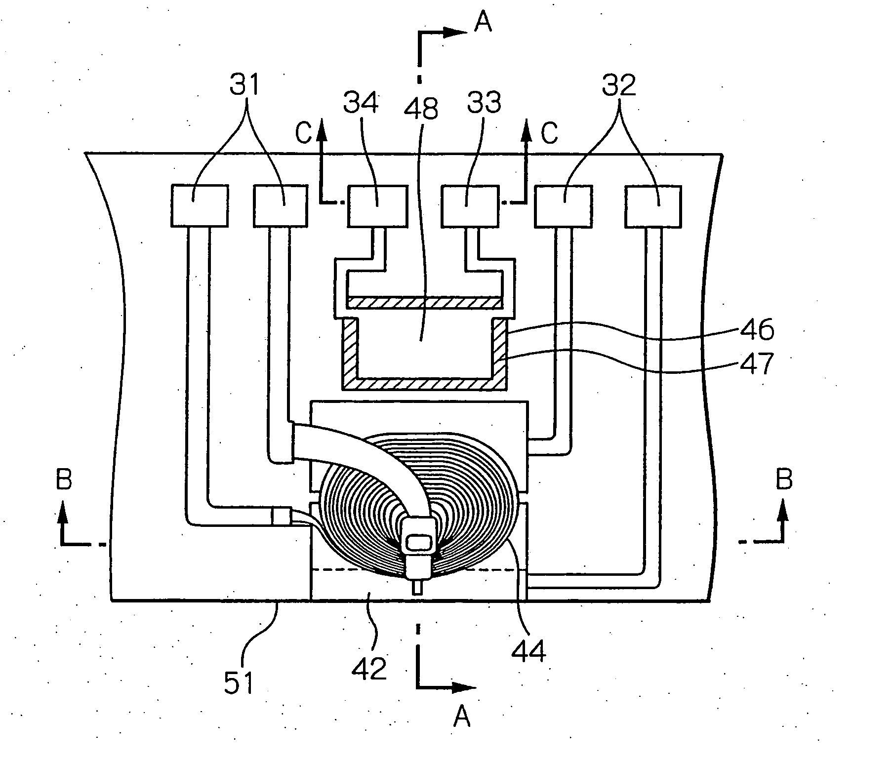
[0010] Therefore, it is an object of the present invention to provide a thin-film magnetic head that the protrusion of the head end surface due to heat generated from the heating means becomes large enough to set the magnetic spacing dMS to the smaller value efficiently at the head end surface adjacent to the ends of the head elements, an HGA provided with this thin-film magnetic head and a magnetic disk drive apparatus provided with this HGA. And it is another object of the present invention to provide a thin-film magnetic head with a heating means by which the required protrusion of the head end surface is obtained with smaller electric power consumption than the conventional art, an HGA provided with this thin-film magnetic head and a magnetic disk drive apparatus provided with this HGA.

Problems solved by technology

Therefore, the difference between the amounts of these protrusions is likely to cause the protruded trailing portion to contact the magnetic disk surface.
As the result, a thermal asperity that is a problem such that the MR read head element outputs abnormal signals due to heat generated by the contact has possibilities to occur.
Further, the contact has a risk of causing physical damage or crash of the magnetic head element and the magnetic disk.
Moreover, because of the existence of the protruded trailing portion, the head end surface adjacent to the end of the magnetic head element needs to be separated from the magnetic disk surface by a required amount, and therefore, the magnetic spacing dMS can not be efficiently set to an adequately small value.
Furthermore, the thin-film magnetic head with the above-mentioned conventional heater can not adapt to lower electric power consumption of the device mounting the magnetic disk drive apparatus.
However, the electric power consumption of the devices must be reduced inevitably, and then, the power supply of the preamplifier for driving the mounted magnetic disk drive apparatus is limited more than ever.
Therefore, in the thin-film magnetic head with the above-mentioned conventional heater, the power required for reducing the magnetic spacing dMS to the predetermined value can not be surely supplied to the heater.
As the result, the head end surface adjacent to the end of the magnetic head element is not protruded to the required extent, and therefore, sufficient writing and reading performances can not be obtained.

Method used


Image

  • Thin-film magnetic head with heating means for adjusting magnetic spacing
  • Thin-film magnetic head with heating means for adjusting magnetic spacing
  • Thin-film magnetic head with heating means for adjusting magnetic spacing

Examples


Embodiment Construction

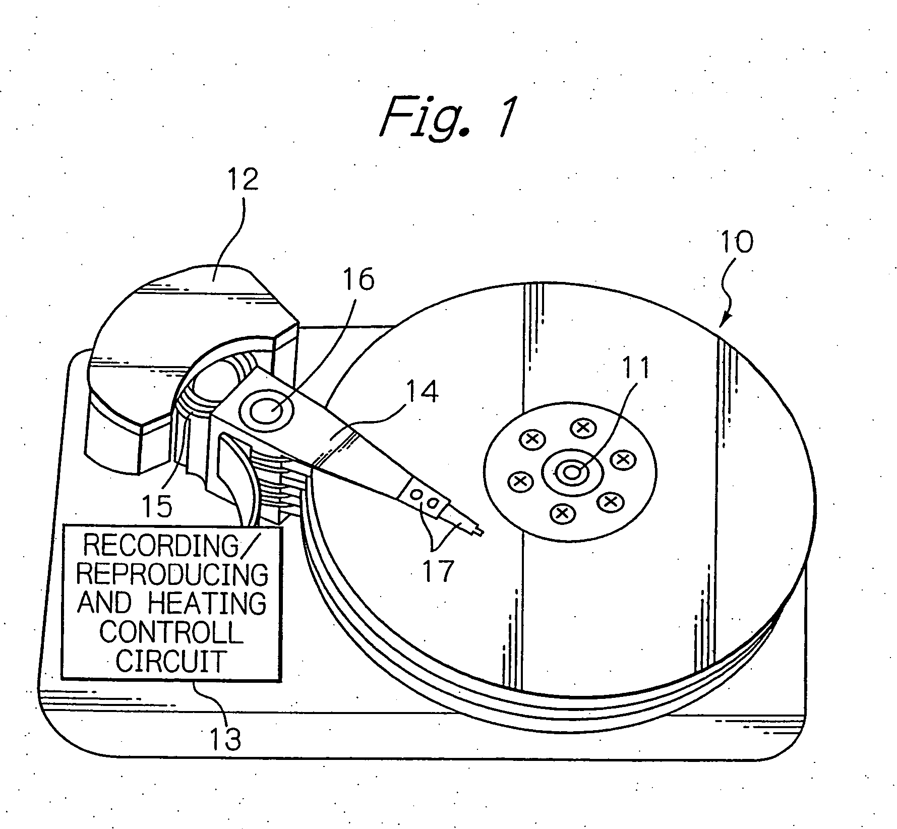
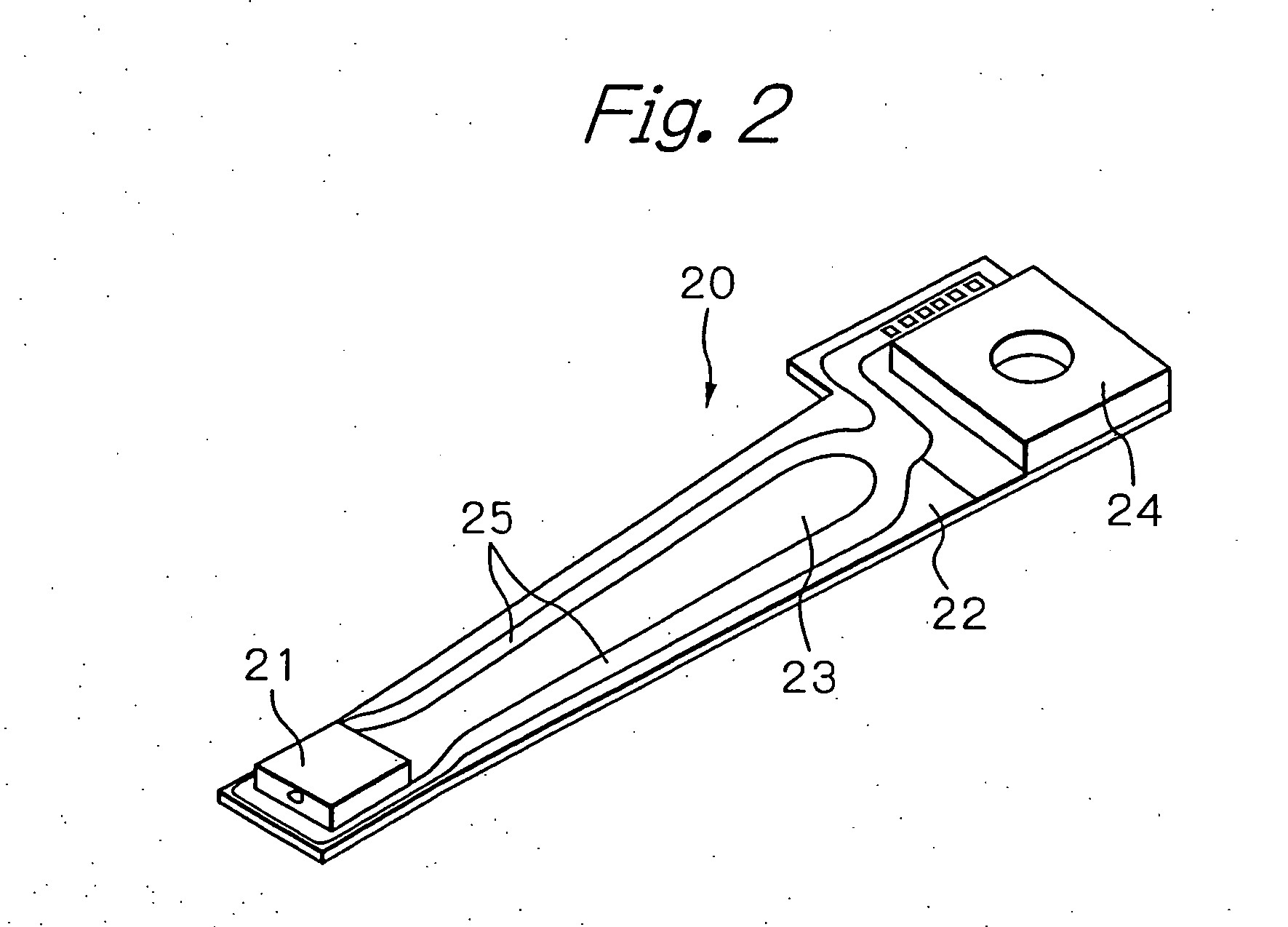
[0041]FIG. 1 shows a perspective view schematically illustrating a structure of a main part of an embodiment of a magnetic disk drive apparatus according to the present invention, FIG. 2 shows a perspective view illustrating an embodiment of an HGA according to the present invention, and FIG. 3 shows a perspective view of an embodiment of a thin-film magnetic head (slider) provided on the end portion of the HGA.

[0042] In FIG. 1, reference numeral 10 indicates a plurality of magnetic disks rotating around a rotational axis of a spindle motor 11, 12 indicates an assembly carriage device for positioning a thin-film magnetic head (slider) on a track, and 13 indicates a recording / reproducing and heating control circuit for controlling read / write operations and heating operations of the thin-film magnetic head, respectively.

[0043] The assembly carriage device 12 is provided with a plurality of drive arms 14. These drive arms 14 are rotatable around a pivot bearing axis 16 by means of a ...


PUM


Abstract

A thin-film magnetic head that the protrusion of the head end surface due to heat generated from the heating means becomes large enough to set the magnetic spacing dMS to the smaller value efficiently is provided. The head comprises: a substrate having an element-formed surface on which at least one concave portion is formed and an ABS; at least one magnetic head element formed above or on the element-formed surface; at least one thermal expansion layer embedded in the at least one concave portion; and at least one heating means positioned directly above the at least one thermal expansion layer.

Description

PRIORITY CLAIM [0001] This application claims priorities from Japanese patent application No. 2004-359775, filed on Dec. 13, 2004 and Japanese patent application No. 2005-157353, filed on May 30, 2005, which are incorporated herein by reference. BACKGROUND OF THE INVENTION [0002] 1. Field of the Invention [0003] The present invention relates to a thin-film magnetic head with a heating means, a head gimbal assembly (HGA) with the thin-film magnetic head and a magnetic disk drive apparatus with the HGA. [0004] 2. Description of the Related Art [0005] In a magnetic disk drive apparatus, when writing or reading signals, a thin-film magnetic head (slider) hydrodynamically flies with a predetermined spacing (flying height) on a rotating magnetic disk. While flying on the magnetic disk, the thin-film magnetic head writes signals to the magnetic disk using magnetic fields generated from an inductive write head element, and reads signals by sensing magnetic fields corresponding to the signal...

Claims


Application Information

Patent Timeline
IPC IPC(8): G11B5/41
CPCG11B5/3136G11B5/314G11B5/4826G11B5/6064G11B5/607G11B5/6005
Inventor SAKAMOTO, TAKAMITSUOIKE, TAROKURIHARA, KATSUKILEUNG, ERIC
Owner TDK CORPARATION
Learn More