Refrigeration air dryer

a technology of refrigerating air dryer and air pipe, which is applied in the direction of defrosting, separation process, and domestic cooling apparatus, etc., can solve the problems of condensation water leading to a puddle on the floor, condensation water can decay, and the performance of the reheater can drop depending upon, so as to achieve high dehumidification performance and effectively use energy

Inactive Publication Date: 2010-04-08
SMC CORP
View PDF0 Cites 11 Cited by
  • Summary
  • Abstract
  • Description
  • Claims
  • Application Information

AI Technical Summary

Benefits of technology

[0019]Basically, it is a technical purpose of the present invention to provide high dehumidification performance with small electric power consumption by reducing the heat exchanger duty Q3 of the condenser in the refrigeration air dryer, i.e., the heat quantity discharged from the condenser, effectively using energy in the conventional refrigeration air dryer, thereby providing an energy-saving refrigeration air dryer.

Problems solved by technology

The conventional air dryer shown in FIG. 2 has a problem in that the performance of the reheater drops depending upon the conditions of use.
This is a major problem of the conventional air dryers.
Accordingly, such an air pipe can decay due to dew condensation water.
Furthermore, the dew condensation water can lead to a puddle on the floor etc.. underneath the bottom of the pipe.
Heat insulation of these pipes requires hard work and high costs.
However, in this case, the air input via the air inlet 20 (primary air) cannot be preliminarily cooled.
However, such methods leads to disadvantages, examples of which include: an increased scale of the dryer; an increased scale of refrigeration equipment (air conditioner, chiller, cooling tower, etc.), an increased energy consumption of the refrigeration equipment.

Method used


Image

  • Refrigeration air dryer
  • Refrigeration air dryer
  • Refrigeration air dryer

Examples


Embodiment Construction

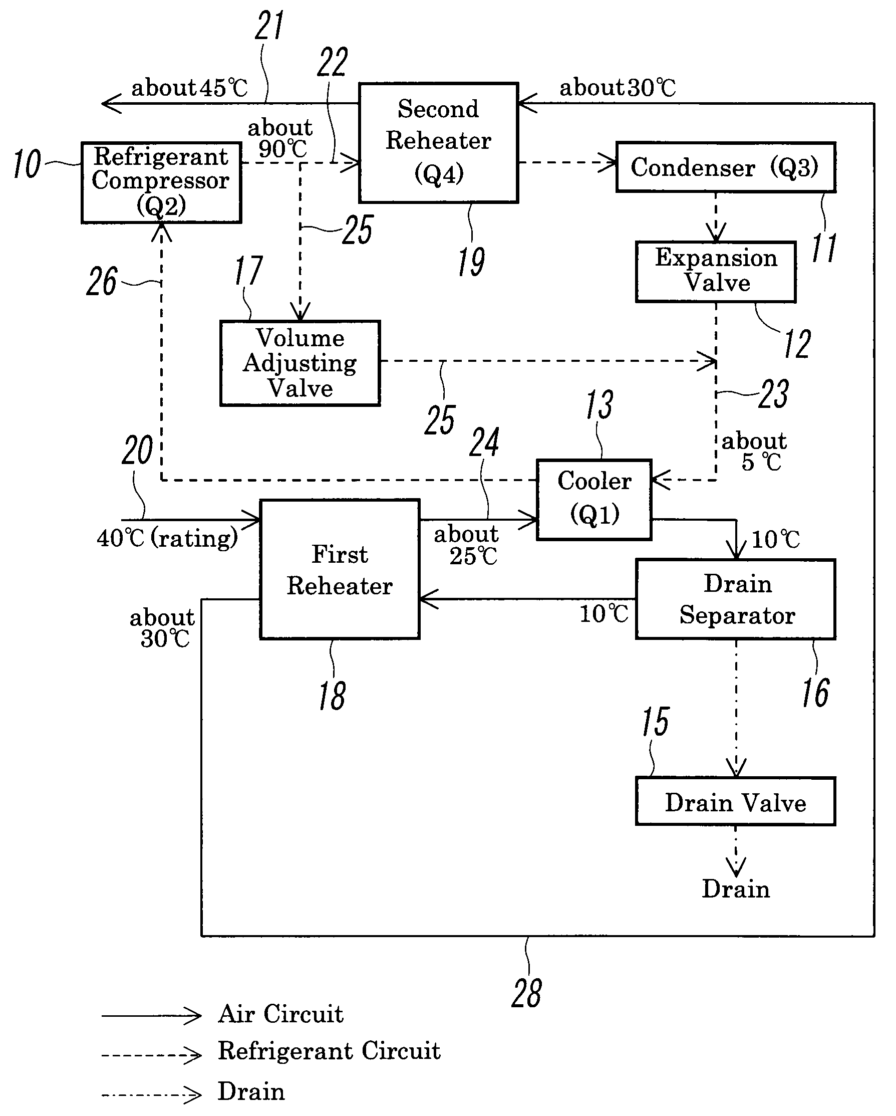
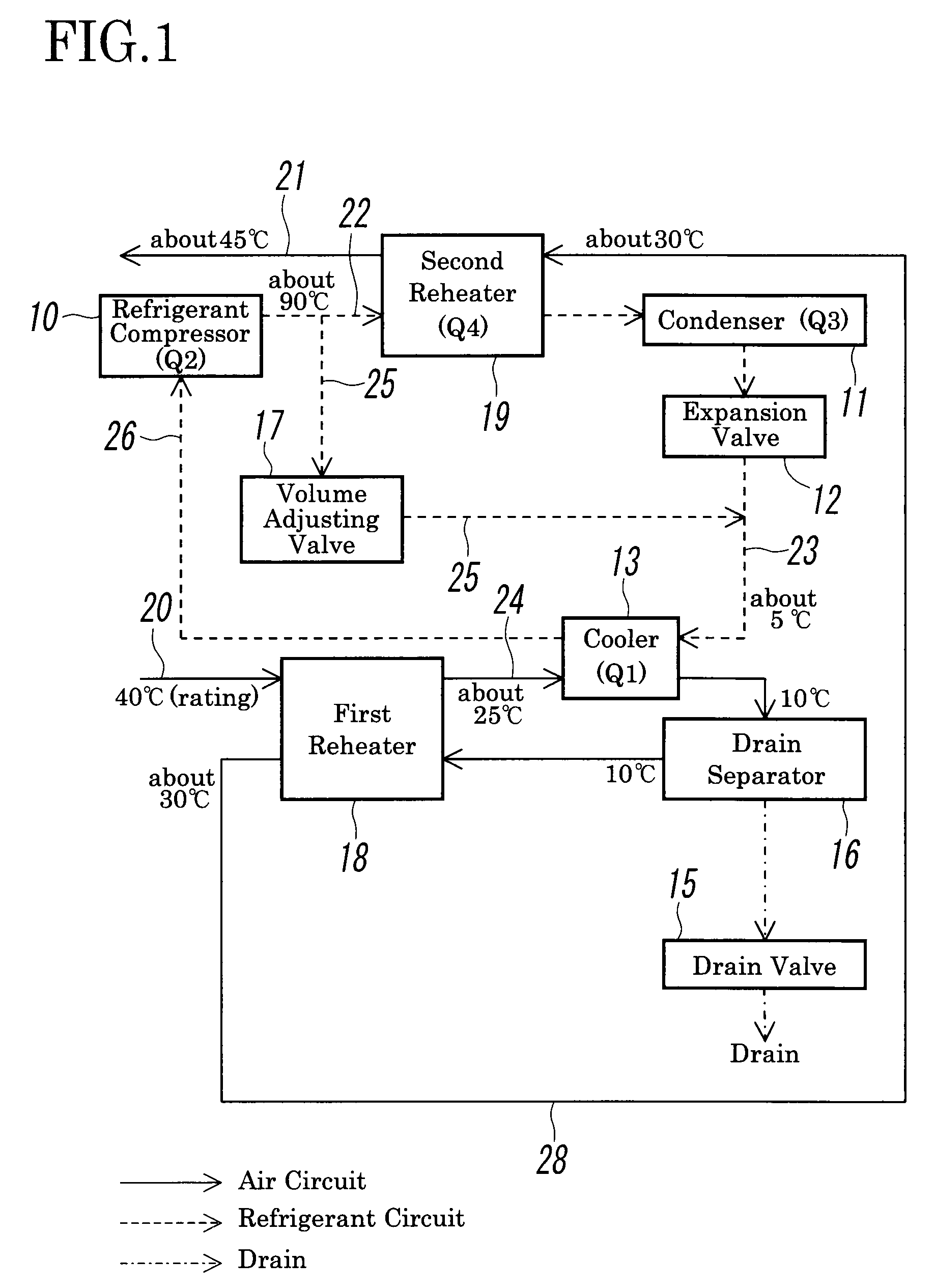
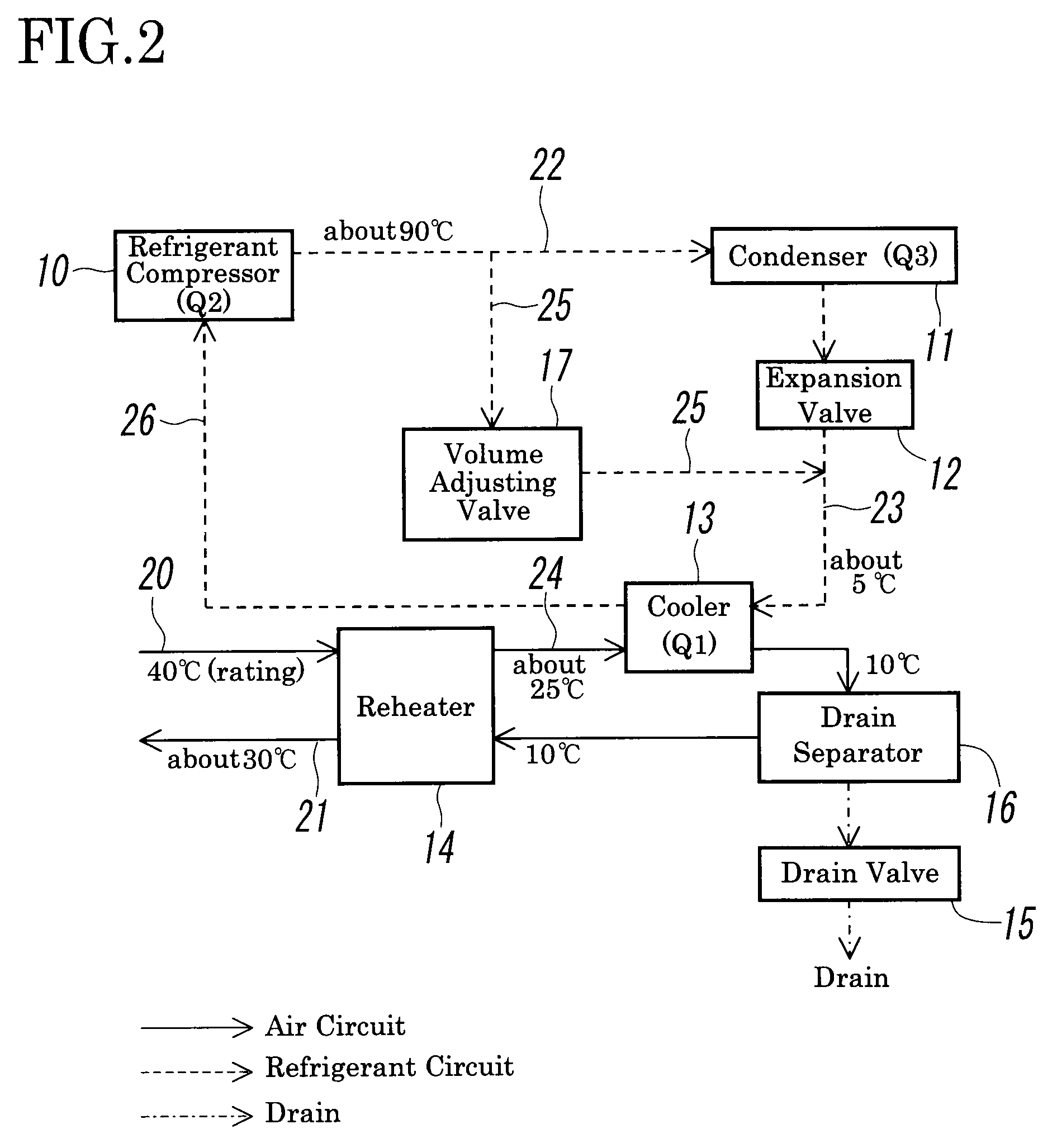
[0028]FIG. 1 shows an embodiment of a refrigeration air dryer according to the present invention. The refrigeration air dryer according to the embodiment includes a refrigerant system and an air system in which several components are the same as those in the conventional refrigeration air dryer shown in FIG. 2. Accordingly, in FIG. 1, the same components as those in FIG. 2 are denoted by the same reference numerals. The major difference between the embodiment and the conventional refrigeration air dryer shown in FIG. 2 is that the embodiment employs a first reheater 18 and a second reheater 19 in order to reduce electric power consumption while maintaining the stable operation of the refrigeration air dryer.

[0029]The refrigerant system in the refrigeration air dryer shown in FIG. 1 includes a refrigerant compressor 10, a condenser 11 which condenses a high-temperature refrigerant which has been compressed by the refrigerant compressor 10 and has been transmitted from a high-temperat...


PUM


Abstract

A refrigeration air dryer, which dehumidifies compressed air by cooling the air at a cooler by exchanging heat with a refrigerant, includes a first reheater and a second reheater. The first reheater has a configuration in which warm and moist primary air to be dehumidified is preliminarily cooled by exchanging heat between the primary air and low-temperature dehumidified air dehumidified by the cooler, and is transmitted to the cooler. At the same time, the temperature of the humidified air is raised, and the humidified air is transmitted to the second reheater. The second reheater has a configuration in which the humidified air having a temperature raised by the first reheater is again raised by exchanging heat with the high-temperature refrigerant compressed by the refrigerant compressor, following which the humidified air is externally discharged as secondary air.

Description

BACKGROUND OF THE INVENTION[0001]1. Field of the Invention[0002]The present invention relates to a refrigeration air dryer which dehumidifies compressed air by condensing moisture in the compressed air by cooling the compressed air.[0003]2. Description of the Related Art[0004]In an air compressor system employing solenoid valves, air cylinders, etc. in order to prevent trouble from occurring due to moisture included in compressed air to be supplied to the air compressor system, the moisture included in the compressed air is preferably removed beforehand. In order to remove such moisture, a refrigeration air dryer is employed.[0005]FIG. 2 shows a circuit of a refrigerant system and an air system in a conventional refrigeration air dryer. The refrigerant system in refrigeration air dryer includes a refrigerant compressor 10, a condenser 11 which condenses a high-temperature refrigerant compressed by the refrigerant compressor 10 and transmitted via a high-temperature refrigerant pipe ...

Claims


Application Information

Patent Timeline
Patent Type & Authority Applications(United States)
IPC IPC(8): F25D21/00F25D21/14
CPCB01D53/265F25B43/00F25B29/00
Inventor AONO, HIDEAKI
Owner SMC CORP
Why Eureka
Try Eureka