
Method and apparatus for system monitoring and maintenance

a monitoring and maintenance system and system technology, applied in the field of diagnostics and maintenance of complex systems, can solve the problems of ambiguous faults, limit the effectiveness of such techniques, and pose significant challenges to monitoring and maintenance systems, and achieve the effect of simulation of system performan

Inactive Publication Date: 2006-06-15
HONEYWELL INT INC
View PDF46 Cites 133 Cited by
  • Summary
  • Abstract
  • Description
  • Claims
  • Application Information

AI Technical Summary

Benefits of technology

[0014] The present invention is directed to a method and an apparatus for intelligent monitoring and maintenance of a system. According to a first aspect of the present invention, a method for intelligent monitoring and maintenance of a system comprises: accessing data relating to functional components of the system; extracting parameter information for functional components of the system, the step of extracting parameter information including performing inferential processing and trend recognition of the data using previous knowledge about the system, and simulating performance of the system using models of the system and previous knowledge about the system; identifying new information about the system present in extracted parameter information; and providing the new information to the step of extracting parameter information, to be used as previously learned knowledg

Problems solved by technology

Existing techniques to monitor and maintain vehicle systems or SIL facilities suffer from a host of technical problems that limit the effectiveness of such techniques.
Diagnosing of faults without clearly identifiable causes, also known as ambiguous faults, pose a significant challenge to monitoring and maintenance systems.
Existing monitoring and maintenance systems have difficulty in correctly isolating the failed LRC in a complex fault with apparent fault symptoms that can be caused by an improper operation, and / or by failures of multiple LRCs.
Faced with such a fault scenario, existing monitoring and maintenance systems will simply report multiple failed LRCs.
No Fault Found reports cast a doubt on the reliability of the vehicle's subsystems and lead to maintenance personnel's loss of faith in onboard diagnostic results.
Subsystem-level Can Not Duplicate faults are especially troublesome and require an in-depth understanding of the performance of the subsystem and its master system.
Can Not Duplicate faults also cast a doubt on the reliability of the vehicle's subsystems.
Even when No Fault Found and Can Not Duplicate faults are resolved, it is often difficult to verify during systems operation that the faults were correctly resolved.
However, the tests performed during system operation can produce highly correlated and complex data that requires a thorough understanding of the system performance in order to decipher anomalies hidden in apparently healthy data.
Personnel maintaining or operating a complex vehicle system or lab facility are often not trained to comprehensively understand the intricacies of the embedded diagnostic logic and system performance data, particularly for a newer system where experience based know-how is not yet present.
Such training deficiencies cause delay in resolution of system operational issues and present an opportunity for healthy Line Replaceable Components being wrongly identified as failed and then replaced.
Due to the above drawbacks, existing techniques for monitoring and maintaining complex systems present significant commercial challenges.
Incorrect or incomplete resolution of system problems and failures add considerable expense to the life cycle costs (LCC) to maintain and operate aircrafts, ships, and lab facilities.
Currently available technology for monitoring and maintaining aircraft systems increase dollar by the hour amounts due to incidences of incorrect or incomplete servicing of the aircraft.
No Fault Found and Can Not Duplicate reports cannot therefore be addressed effectively enough, as there is no clear information as to what fault model and component might have caused them.

Method used


Image

  • Method and apparatus for system monitoring and maintenance
  • Method and apparatus for system monitoring and maintenance
  • Method and apparatus for system monitoring and maintenance

Examples


Embodiment Construction

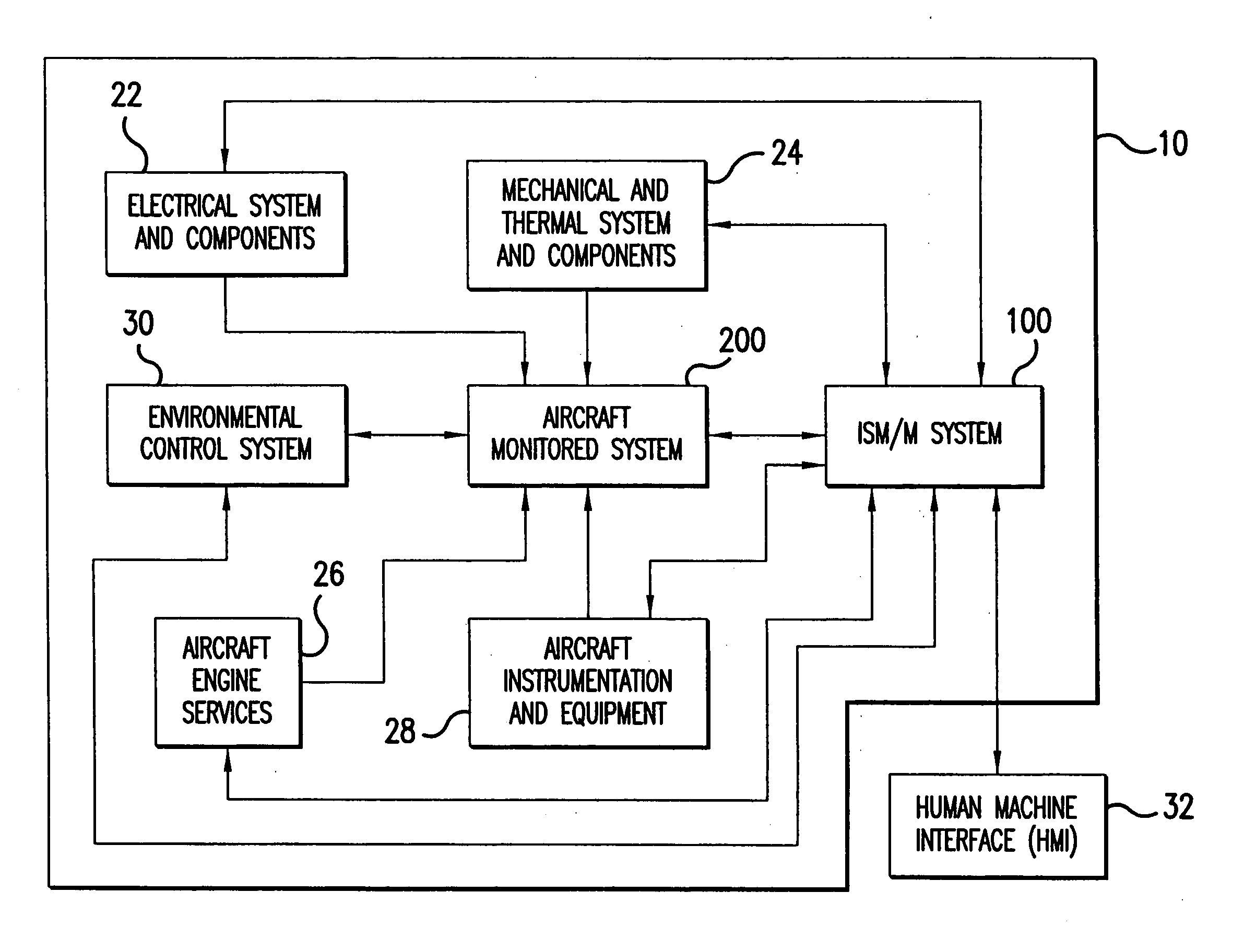
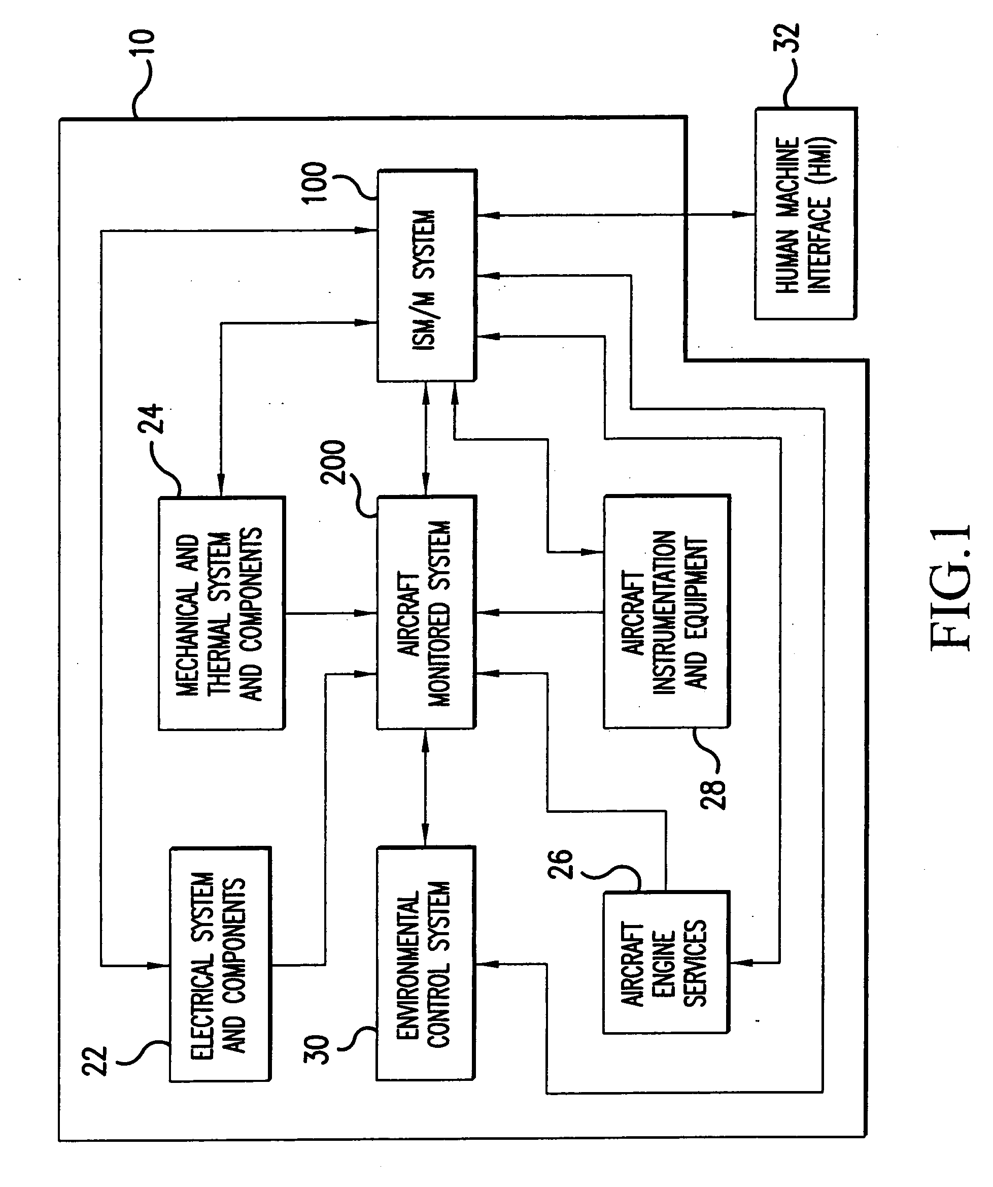
[0033] Aspects of the invention are more specifically set forth in the accompanying description with reference to the appended figures. Although aspects of the present invention are described and illustrated in the context of a vehicle environmental control system (ECS), it should be recognized that principles of the present invention are not limited to such an environment. FIG. 1 is a block diagram of a typical aircraft system 10 containing an intelligent systems maintenance / monitor (ISM / M) system 100 according to an embodiment of the present invention. Aircraft system 10 illustrated in FIG. 1 includes the following components: electrical system and components 22; mechanical and thermal system and components 24; aircraft engine services 26; aircraft instrumentation and equipment 28; environmental control system 30; aircraft monitored system 200; and ISM / M system 100. A human machine interface (HMI) 32 is provided for input / output of information and commands to / from the ISM / M system...


PUM


Abstract

A method and an apparatus provide intelligent monitoring and maintenance of a system. The method according to one embodiment accesses data relating to functional components of the system; extracts parameter information for functional components of the system, the step of extracting parameter information including performing inferential processing and trend recognition of the data using previous knowledge about the system, and simulating performance of the system using models of the system and previous knowledge about the system; identifies new information about the system present in extracted parameter information; and provides the new information to the step of extracting parameter information, to be used as previous knowledge.

Description

CROSS REFERENCE TO RELATED APPLICATION [0001] The present application claims priority under 35 USC §119(e) to U.S. Provisional Application No. 60 / 625,172 filed Nov. 5, 2004, which is hereby incorporated by reference herein in its entirety.BACKGROUND OF THE INVENTION [0002] 1. Field of the Invention [0003] The present invention relates to diagnostics and maintenance of complex systems, especially applicable to vehicle systems, and more particularly to a method and apparatus providing intelligent systems monitoring and maintenance. [0004] 2. Description of the Related Art [0005] Complex systems such as industrial facilities, or airborne, terrestrial and marine vehicles, are monitored for maintenance purposes and operated by complex control systems. Such control systems are responsible for the operational health, correct maintenance, and general functions of the vehicle or industrial facility. Examples of control systems that also support maintenance and monitoring are an environmental...

Claims


Application Information

Patent Timeline
IPC IPC(8): H04L12/50
CPCG05B13/042G05B23/0245H04L41/0853H04L41/0856H04L41/0866H04L41/147Y04S40/162Y04S40/00H04L41/149
Inventor PEREIRA, ASHLEY A.JAVED, MUHAMMAD ASHRAFLAM, CHUN HOYUEN, CHUNG-YAN
Owner HONEYWELL INT INC
Learn More