
Eureka
For R&D, Eureka makes reading and utilizing patents & technical documents easy.
Eureka AIR
Designed for self-driven R&D workflows. Generate viable solutions, solve complex R&D challenges, empower your innovation with AI.

Eureka Materials
Designed for material experts only. Revolutionize your material R&D, from search, analyze, to developing new materials.

TechResearch
Generate reliable direction feasibility study reports for your R&D in just a few steps.

TechSeek
Discover and master advanced knowledge NOW. Basics, ideas, possibilities, all at once.

TechMind
As an expert in R&D Theories, TechMind can generates customized viable solutions instantly.

TechRisk
Analyze your overall solution with one click, know your potential R&D risks in advance.

TechMonitor
Get weekly tech updates, stay abreast of the latest tech innovations and key insights.
Servo tapping unit with built in shock protection
- Summary
- Abstract
- Description
- Claims
- Application Information
AI Technical Summary
Benefits of technology
Problems solved by technology
Method used
Image

Examples
second embodiment
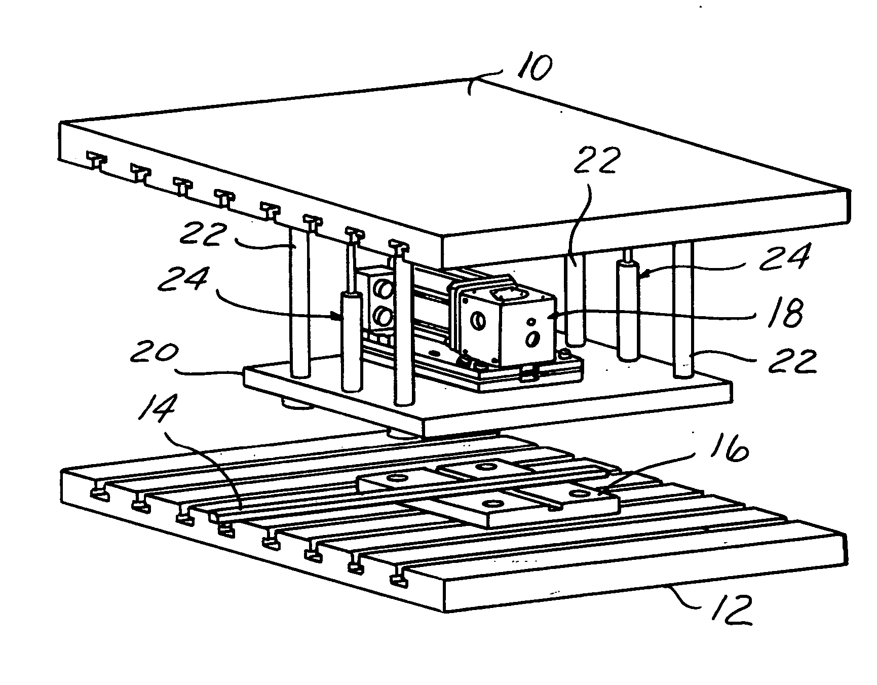
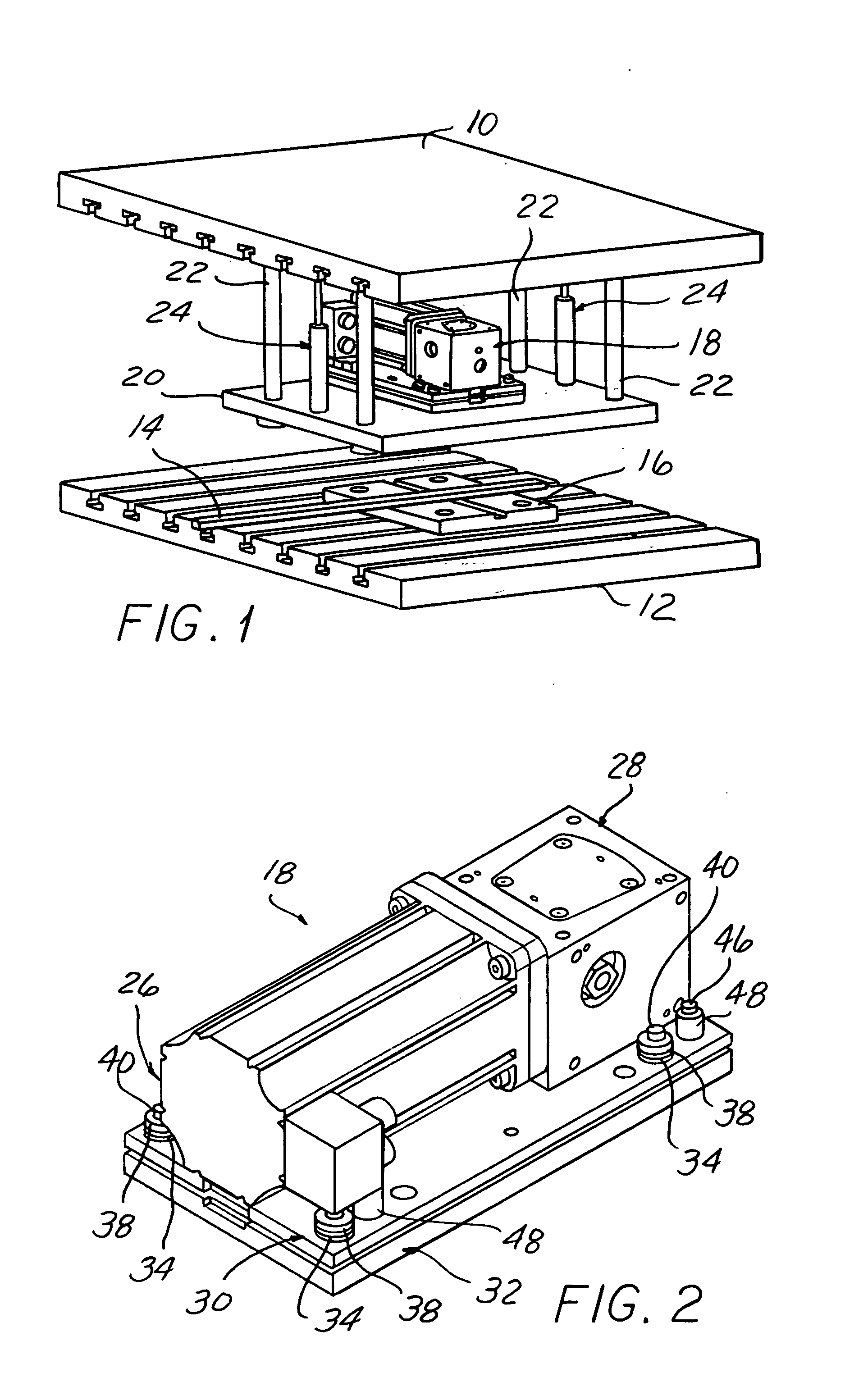
[0055]FIGS. 5-8 show the invention featuring a servo tapping unit 68 in which a servo motor 70 is vertically oriented within a press, mounted on a stripper plate 72 suspended from the press upper platen 10 as in the first described embodiment.
[0056] A base structure comprising a housing 74 is attached to the stripper plate 72 which supports the servo motor 70 with an interposed shock plate 76.
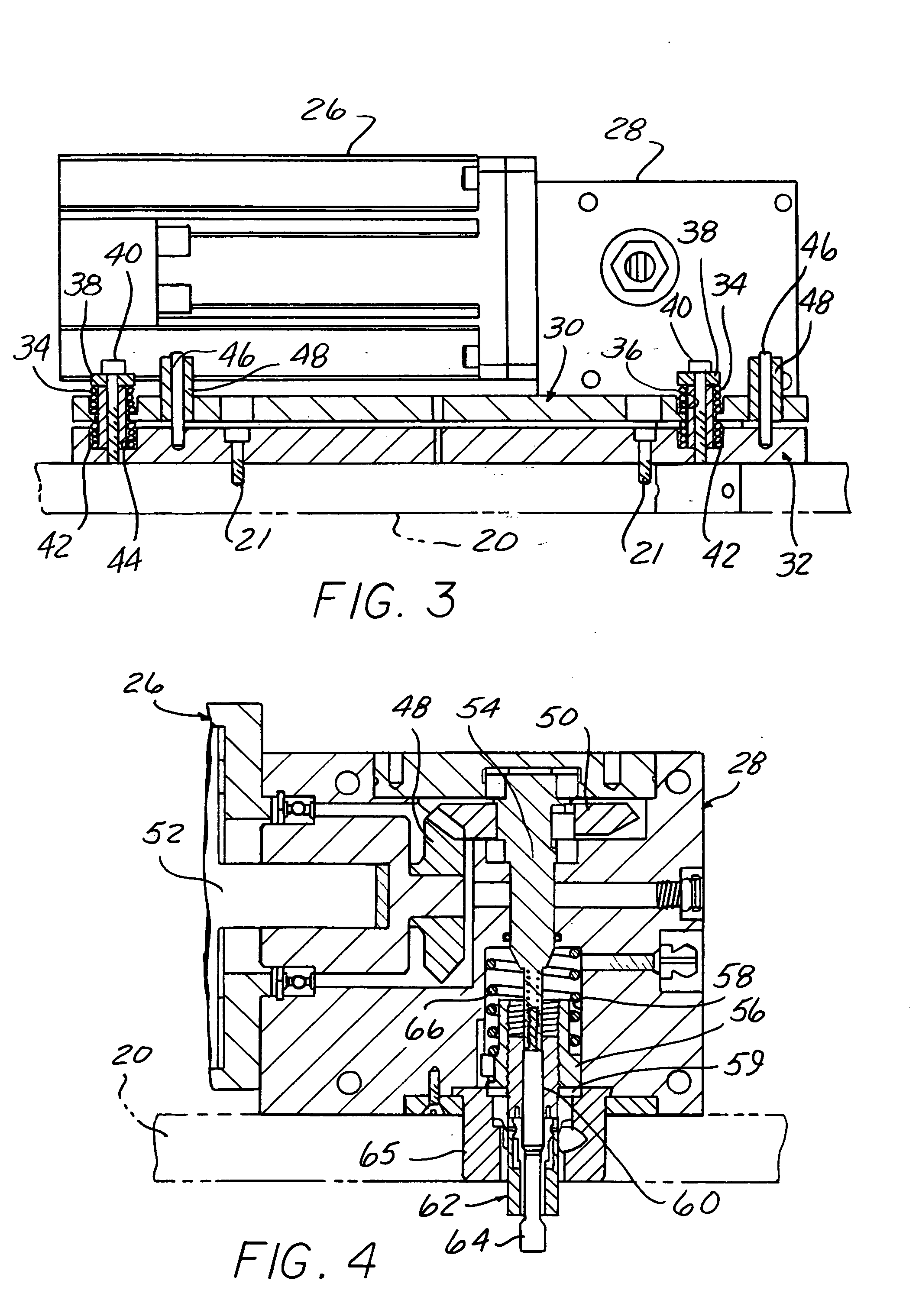
[0057] The interposed shock plate 76 is floatingly supported at a spaced location above the base housing 74 by two opposing sets of four springs each. A first set of springs 78 are each received in a respective upwardly facing counterbore 80 in the shock plate 76, compressed beneath a headed screw 82 threaded into a hole in the top of the base 74 to act to urge the shock plate 76 downwardly.
[0058] A second set of four springs 84 are each received in a downwardly facing counterbore 86 in the shock plate 76 compressed against the upper surface of the base housing 74 to urge the shock plate upwa...
third embodiment
[0063]FIGS. 9-14 show a tapping unit with shock protection according to the invention.
[0064] In this embodiment, a vertically oriented servo motor 96 is mounted on a base structure comprising a housing 98 with a floating interposed shock plate 100.
[0065] A tap holder and drive housing 102 is mounted on a housing section offset horizontally from the axis of the servo motor 96.
[0066] The shock plate 100 is resiliently float mounted above the housing 98 as in the other embodiments with two opposing sets of four springs. A first set of four springs 102 are received in respective upward facing counterbores 104. The springs 102 are compressed against end walls at the bottom of counterbores 104 by the heads of screws 106 threaded into the base housing 98 to urge the shock plate 100 downwardly. A set of spacer-bushings 108 limit the extent of compression of the springs 102.
[0067] A second opposing set of four springs 110 are received in downwardly facing bores 112 in the shock plate 100 ...
PUM
| Property | Measurement | Unit |
|---|---|---|
| Acceleration | aaaaa | aaaaa |
Abstract
Description
Claims
Application Information
 - R&D Engineer
- R&D Manager
- IP Professional
- Industry Leading Data Capabilities
- Powerful AI technology
- Patent DNA Extraction
Browse by: Latest US Patents, China's latest patents, Technical Efficacy Thesaurus, Application Domain, Technology Topic, Popular Technical Reports.
© 2024 PatSnap. All rights reserved.Legal|Privacy policy|Modern Slavery Act Transparency Statement|Sitemap|About US| Contact US: help@patsnap.com