
Electrically-conductive hose

a tubular polymer and electrically conductive technology, applied in the direction of synthetic resin layered products, transportation and packaging, other domestic articles, etc., can solve the problems of affecting the strength and flexibility of the hose, limiting the use of certain resin and fillers, and gas or other fluid to be conveyed

Inactive Publication Date: 2006-06-15
PARKER HANNIFIN CORP
View PDF12 Cites 51 Cited by
  • Summary
  • Abstract
  • Description
  • Claims
  • Application Information

AI Technical Summary

Benefits of technology

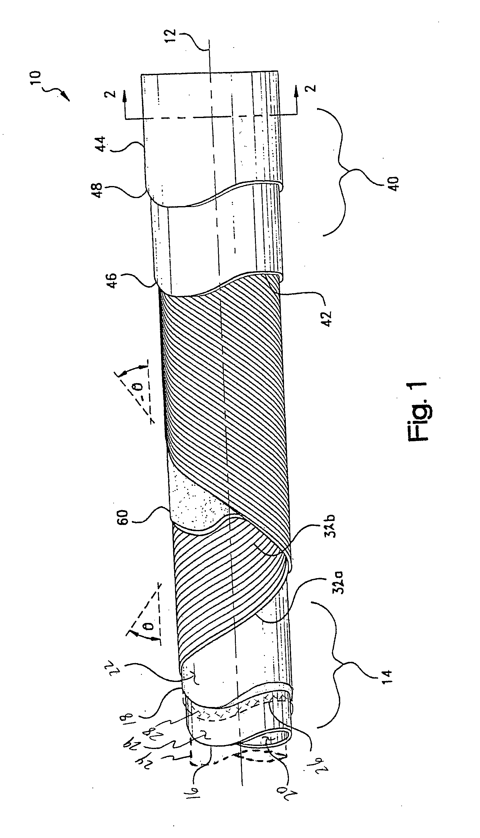
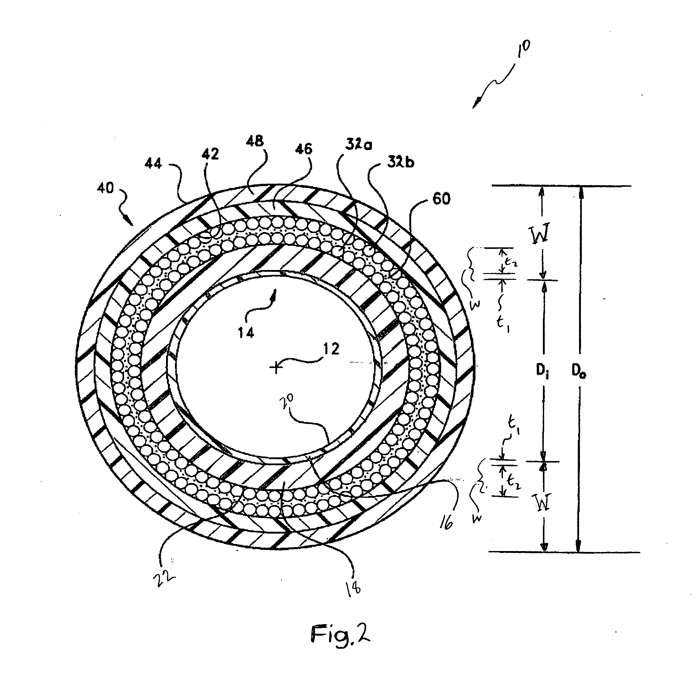
The present invention is about a new type of electrically-conductive tubular polymeric composite that can be used as a core tube in hoses for delivering fuel and other gases. The composite is made up of a double or multi-layer construction, with a layer of carbon black-filled polyether block amide (PEBA) resin providing high electrical conductivity and good chemical resistance. The PEBA resin layer can be loaded with a more structured carbon black without compromising its physical properties, making it suitable for use in applications where high conductivity is required. The composite is small-diameter tubular, flexible, and can be used in low-volumetric throughput hoses. It is especially useful in applications where the hose needs to be electrically conductive, such as for delivering CNG.

Problems solved by technology

Particularly in the case of such small diameter tubing, it is believed to heretofore have been problematic to impart sufficient conductivity, typically measured as a surface resistance or resistivity, to such tubing using conventional techniques so as to render the tubing suitable for certain applications.
In this regard, the gas or other fluid to be conveyed may limit the use of certain resin and fillers, particularly metal particles.
The use of higher filler loading levels also can affect the strength and flexibility of the hose, as well as presenting problems in the extrusion of the tube.

Method used


Image

  • Electrically-conductive hose
  • Electrically-conductive hose
  • Electrically-conductive hose

Examples


Embodiment Construction

[0020] Certain terminology may be employed in the description to follow for convenience rather than for any limiting purpose. For example, the terms “forward,”“rearward,”“right,”“left,”“upper,” and “lower” designate directions in the drawings to which reference is made, with the terms “inward,”“interior,”“inner,” or “inboard” and “outward,”“exterior,”“outer,” or “outboard” referring, respectively, to directions toward and away from the center of the referenced element, and the terms “radial” or “horizontal” and “axial” or “vertical” referring, respectively, to directions, axes, planes perpendicular and parallel to the central longitudinal axis of the referenced element, and the terms “downstream” and “upstream” referring, respectively, to directions in and opposite that of fluid flow. Terminology of similar import other than the words specifically mentioned above likewise is to be considered as being used for purposes of convenience rather than in any limiting sense.

[0021] In the f...


PUM

PropertyMeasurementUnit
pressuresaaaaaaaaaa
inner diameteraaaaaaaaaa
thicknessaaaaaaaaaa

Abstract

Tubular polymeric composite for articles such as tubing and hoses. The composite is formed of a tubular first layer of a thermoplastic block polyether amide resin (PEBA) filled with a more structured carbon black particulate filler to render it electrically-conductive, and a tubular second layer of a thermoplastic polyamide, polyester, polyolefins, or other thermoplastic resin compatible with the PEBA resin of the first material, and which second material optionally may be filled with a less structured carbon black particulate filler to render it electrically-conductive.

Description

CROSS-REFERENCE TO RELATED CASES [0001] The present application claims the benefit of the filing date of U.S. Provisional Application Ser. No. 60 / 636,045; filed Dec. 14, 2004, the disclosure of which is expressly incorporated herein by reference.BACKGROUND OF THE INVENTION [0002] The present invention relates broadly to multi-layer, electrically-conductive tubular polymeric composites and to articles such as hoses and tubing, which may be straight or coiled, constructed thereof, and more particularly to such composites used as core tubes in such articles as hose for use in the delivery of compressed natural gas (CNG) and other fuel, or in other applications requiring some degree of electrical conductivity for static dissipation or electrical grounding. [0003] Thermoplastic tubing and hose is used in a variety of fluid transfer applications. In basic structure, tubing and hoses of the type herein involved typically are constructed as having a tubular, innermost core. In reinforced co...

Claims


Application Information

Patent Timeline
Patent Type & Authority Applications(United States)
IPC IPC(8): F16L11/04
CPCF16L11/127F16L11/082Y10T428/1393Y10T428/1352Y10T428/139
Inventor FISHER, WILLIAM C.
Owner PARKER HANNIFIN CORP
Learn More