Floor matting

a technology for floor mats and paving, applied in the field of floor mats, can solve the problems of layer delamination, two or more mat layers can be a problem, and the delamination of the layers can not be solved without success, and achieve the effect of reducing delamination

Active Publication Date: 2006-06-15
PARALLAX GROUP INT
View PDF14 Cites 70 Cited by
  • Summary
  • Abstract
  • Description
  • Claims
  • Application Information

AI Technical Summary

Benefits of technology

[0011] The undulating nonplanar boundary resists delamination of the two layers. By having an undulating boundary between the two layers, shear forces and compressive forces applied to one layer are partially converted to compressive forces and tension forces. For example, if one layer is placed in shear with re

Problems solved by technology

The prior art has attempted to make matting with one color on one side and another color on the other side, but without success.
Delamination of two or more mat layers can be a problem especially with use or when there are temperature changes, such as from ambient temperature to below freezing or from ambient temperature to an elevated temperature.
In addition, running and stopping or quick turns on matting, applies shear forces to each of the layers which can lead to delamination of the layers.
With use, the working surface or top surface of the floor matting can become disfigured with stains from

Method used


Image

  • Floor matting
  • Floor matting

Examples


Embodiment Construction

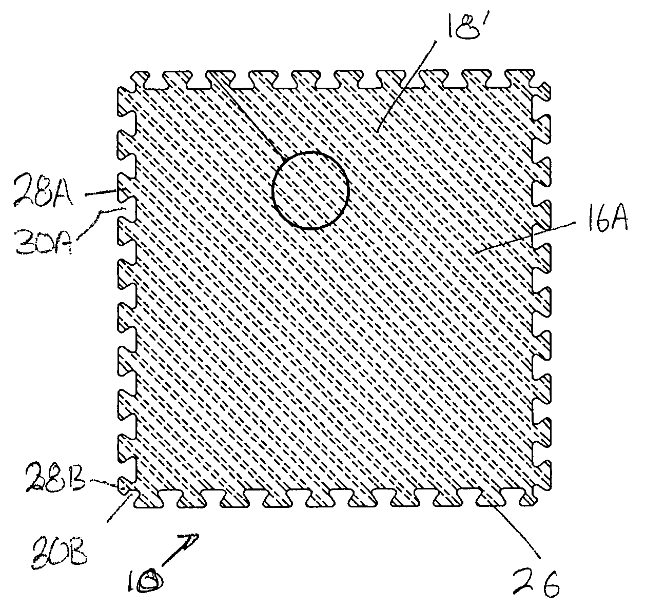
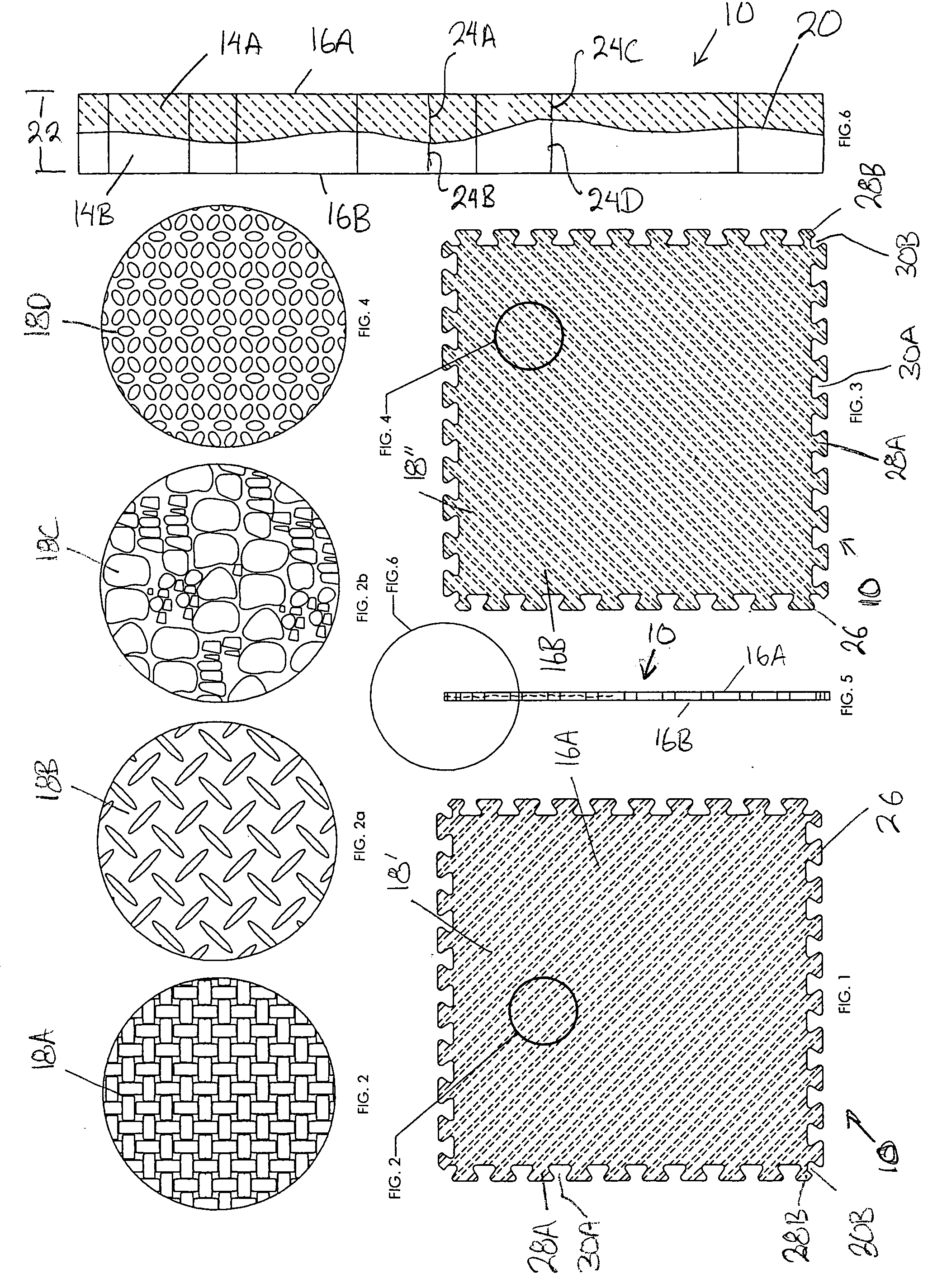
[0020] Referring to FIGS. 1 and 3, the floor mat 10 is a large, planar, flat, body 12 which has a first surface 16A and a second opposing parallel surface 16B. The two surfaces 16A and 16B are parallel to one another. The periphery of the floor mat is bounded by an interlocking perimeter 26. The surface 16A has a texture or three dimensional design and the second surface 16B has a texture or three dimensional design, the two textures or designs can be the same or different. For purposes of this invention, texture means a three dimensional texture or design embossed in or embossed out of the mat surface. One or both surfaces 16A and 16B can also be smooth. The body is made up of two layers 14A and 14B (see FIG. 6). The two layers are bound together either by heat welding and / or an adhesive. Preferably, the two layers have the same chemical composition so that the two layers have the same coefficient of thermal expansion and the same elastomeric properties so that the two layers work ...


PUM

PropertyMeasurementUnit
Thicknessaaaaaaaaaa
Coloraaaaaaaaaa
Lengthaaaaaaaaaa

Abstract

Floor mats comprising two layers bonded together with an undulating boundary between them. The surface color and/or surface texture of the first layer being different from the surface color and/or surface texture of the second layer. The mats having an interlocking periphery boundary adapted so the mats can be interlocked with adjoining mats to form a continuous planar mat flooring.

Description

[0001] This is a continuation-in-part of U.S. patent application Ser. No. 29 / 203,027, filed Apr. 8, 2004. [0002] The application Ser. No. 29 / 203,027, filed Apr. 8, 2004, in its entirety is incorporated by reference into this application.FIELD OF THE INVENTION [0003] The present invention is directed to floor matting. More specifically, the present invention is directed to resilient floor matting which can be used in playroom environments, athletic environments such as for gymnastics or tumbling, and for environments where cushioning from the hard undersurface is desirable, such as a studio, or workplace where people are standing for prolonged periods. Artists, draftsmen, wood workers, printers, surgeons, dentists, retail sales people, and the like, are subject to standing on hard surfaces for prolonged periods. BACKGROUND OF THE INVENTION [0004] Resilient floor matting has been used extensively for thousands of years. Fiber matting was first used, then came carpeting. Between the 19...

Claims


Application Information

Patent Timeline
IPC IPC(8): B32B3/00
CPCB32B3/02Y10T428/24612B32B3/263B32B3/30B32B5/18B32B5/32B32B25/04B32B25/14B32B2250/02B32B2250/22B32B2266/0221B32B2266/025B32B2266/0278B32B2307/404B32B2471/04E01C13/045E01C2201/14E04F15/10E04F2201/095B32B3/06E04F15/105A47G27/0218B32B3/10A47G27/0206A47G27/0275A47G27/0293B32B2307/402
Inventor THRUSH, BRUCE A.
Owner PARALLAX GROUP INT
Why Eureka
Try Eureka