Photoresist coating to apply a coating to select areas of a medical device

a medical device and photoresist technology, applied in the field of methods and systems for coating a medical device, can solve the problems of difficult to tightly control the specific areas of the medical device that receive the coating and the thickness of the coating, and achieve the effect of reducing delamination

Inactive Publication Date: 2012-09-04
BOSTON SCI SCIMED INC
View PDF23 Cites 0 Cited by
  • Summary
  • Abstract
  • Description
  • Claims
  • Application Information

AI Technical Summary

Benefits of technology

[0023]In an exemplary embodiment of the present invention, the thickness of the coating formed by the coating material may be controlled, for example, to assure a thinner layer at an end or edge of the stent. A feathered stent edge could minimize delamination by creating a more compliant interface, for example, on a high strain region of a stent, such as the inside of a hinge portion. A different coating thickness on different portions of the stent may be achieved by exposing different portions of the coated stent to radiation having a different wavelength and / or amplitude such that upon exposure to a solvent for a predetermined amount of time different amounts of coating material are removed from the differently treated portions of the stent. Alternatively, rather than varying the wavelength and / or amplitude of the radiation used, different photoresist coating materials may be used on different portions of the stent, which are removable at different rates upon exposure to a given solvent. In another exemplary embodiment, different coating thicknesses may be achieved by selectively exposing the different portions of a stent coated with a given photoresist coating material to different solvents or to a single solvent for different lengths of time.

Problems solved by technology

Given the often complex geometry of the medical device and the fluid nature of the coating it is difficult to tightly control the specific areas on the medical device that receive coating and the thicknesses of the coating.

Method used


Image

  • Photoresist coating to apply a coating to select areas of a medical device
  • Photoresist coating to apply a coating to select areas of a medical device
  • Photoresist coating to apply a coating to select areas of a medical device

Examples


Embodiment Construction

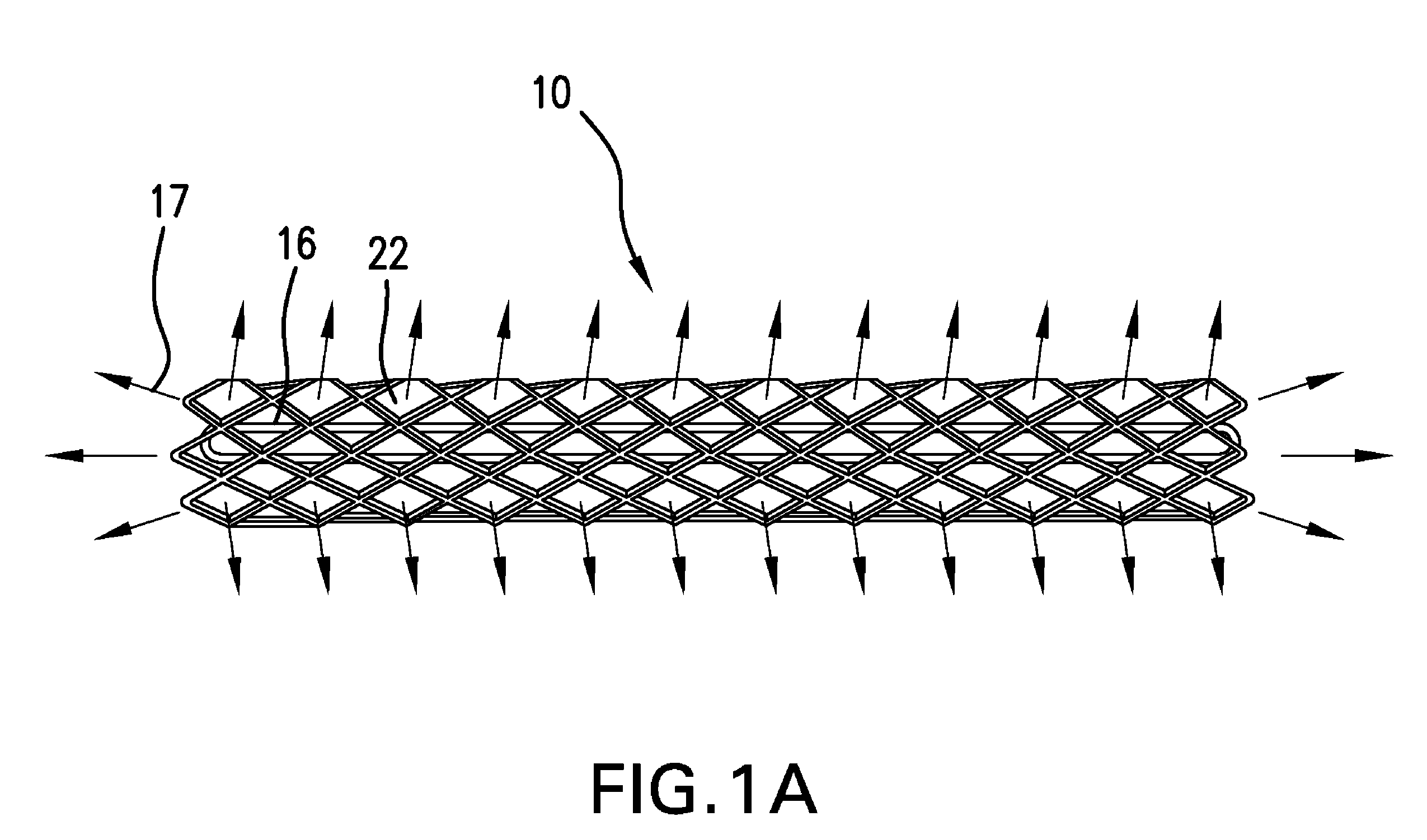
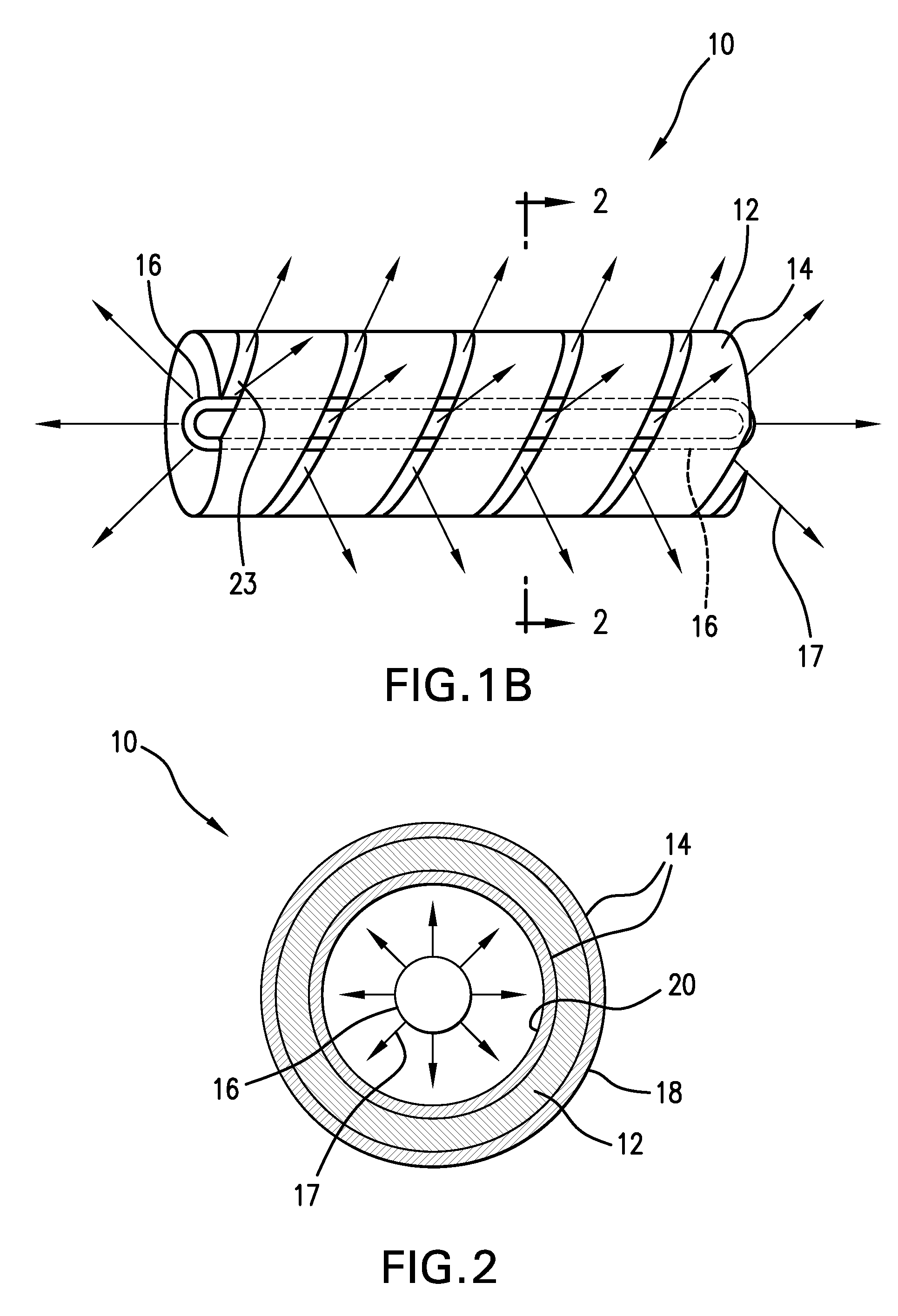
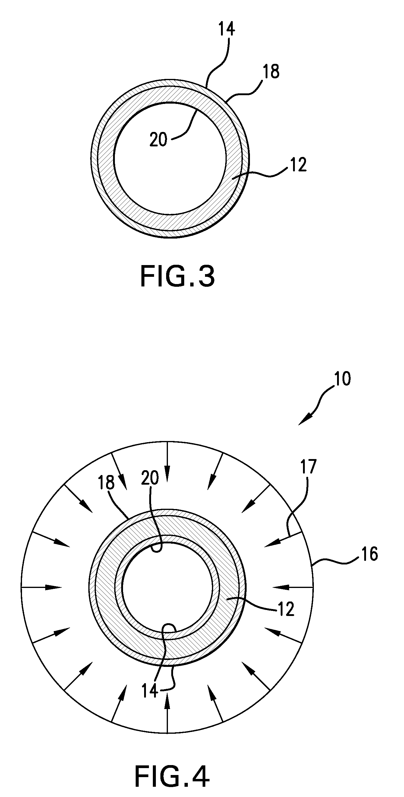
[0030]FIGS. 1A and 1B illustrate exemplary embodiments of a system 10 according to the present invention for coating a medical device, such as a stent 12. Stent 12 is coated with a coating material 14, such as a polymeric photoresist coating.

[0031]An example of a negative photoresist that is biocompatible would include a formulation containing an oligomer with acrylate reactive end groups. The middle portion of this oligomer with acrylate end groups can contain alternatively hydrophilic, non-thrombogenic components or hydrophobic non-thrombogenic components. An example of a hydrophilic non-thrombogenic composition would include materials such as oligoethyleneoxide or copolymers of phosphoryl choline. An example of more hydrophobic non-thrombogenic compositions would include an oligo-isobutylene material.

[0032]An example of a photocrosslinkable system based on photoacid generation is the system of a copolymer of hydroxyethyl methacrylate with methyl methacrylate. The hydroxl groups c...


PUM

PropertyMeasurementUnit
temperatureaaaaaaaaaa

Abstract

Methods and devices for coating a medical device, such as a stent, including the steps of coating the medical device with a photoresist polymeric coating, irradiating a portion of the medical device, optionally applying a post-exposure bake step, and removing all or a portion of the coating from the irradiated portion of the medical device, if a positive photoresist coating material is used, or from a portion of the medical device not exposed to the radiation, if a negative photoresist coating material is used. The photoresist polymeric coating may optionally include a drug.

Description

CROSS-REFERENCE TO RELATED APPLICATIONS[0001]This application claims priority to U.S. Provisional Application No. 60 / 923,016, filed Apr. 11, 2007, the disclosure of which is hereby incorporated by reference.FIELD OF THE INVENTION[0002]The present invention relates to methods and systems for coating a medical device, such as a stent.BACKGROUND INFORMATION[0003]Medical devices are used for a number of purposes, including the reinforcement of recently re-enlarged lumens, the replacement of ruptured vessels, and the treatment of disease such as vascular disease by local pharmacotherapy, i.e., delivering therapeutic drug doses to target tissues while minimizing systemic side effects. Such localized delivery of therapeutic agents has been achieved using medical implants, such as stents, which both support a lumen within a patient's body and place appropriate coatings containing absorbable therapeutic agents at the implant location. Examples of such medical devices that can be used for loc...

Claims


Application Information

Patent Timeline
Patent Type & Authority Patents(United States)
IPC IPC(8): B05D3/06B05D5/00A61F2/06
CPCB05D3/06B05D1/32A61F2250/0067A61F2310/0097Y10T428/31B05D3/065
Inventor EDELMAN, PETER
Owner BOSTON SCI SCIMED INC
Why Eureka
Try Eureka