Durable solar mirror films

Active Publication Date: 2015-04-23
3M INNOVATIVE PROPERTIES CO
View PDF2 Cites 0 Cited by
  • Summary
  • Abstract
  • Description
  • Claims
  • Application Information

AI Technical Summary

Benefits of technology

The patent texts describe the technical problem of metalized polymer films used in concentrated solar power units and concentrated photovoltaic cells being subject to continuous exposure to harsh environmental conditions and the challenge of achieving long-term durability. The inventors of the present invention have developed a solution involving the use of a multilayer optical film as the weatherable layer in the mirror film construction. This solution reduces or eliminates stress differential caused by the disparity in coefficients of hygroscopic expansion of the prior art weatherable layer and the metal reflective layer which leads to tunneling and delamination. The metalized polymer films with the multilayer optical film as the weatherable layer have an increased life and decreased cost of solar power generation.

Problems solved by technology

Consequently, a technical challenge in designing and manufacturing metalized polymer reflective films is achieving long-term (e.g., 20 years) durability when subjected to harsh environmental conditions.
The inventors of the present disclosure recognized that many of the technical problems in forming a durable metalized polymer film capable of long-term outdoor use that retains its optical performance arise from the fundamental mismatch in the physical and chemical nature and properties of metals and polymers.
One particular difficulty relates to ensuring good adhesion between the polymer layer and the metal reflective surface.
Without good adhesion between these surfaces / layers, delamination occurs.
One of the most challenging problems is related to stress at the metal / polymer interface.
Once the stress becomes too great, buckling can occur, causing the polymer layer to delaminate from the metal reflective layer.
Further, when metalized polymer films are cut, their edges may be fractured and unprotected.
Corrosion of metalized polymers typically begins at their edges.

Method used


Image

  • Durable solar mirror films
  • Durable solar mirror films
  • Durable solar mirror films

Examples


examples

[0081]Test Methods:

[0082]Coefficient of Hygroscopic Expansion (CHE):

[0083]Hygroscopic expansion was measured using a dynamic mechanical analyzer (DMA) (model “Q800” obtained from TA Instruments) coupled with a DMA-RH accessory (obtained from TA Instruments). Displacement (in m / m) was measured over a ramp of varying relative humidities, ranging from about 20% to about 80% at a constant temperature of 25° C. Changes in the sample dimensions caused by humidity changes are used to calculate the CHE. Results are expressed in parts per million (ppm) per percent relative humidity (% RH).

[0084]Neutral Salt Spray Test (NSS)

[0085]Corrosion of the comparative and examples was evaluated following the procedure outlined on ISO 9227:2006, “Corrosion tests in artificial atmospheres—Salt spray tests” with the exception that results are reported as visual observations after various times.

example 1

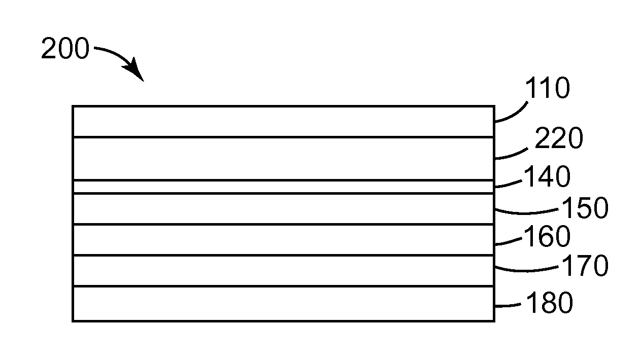
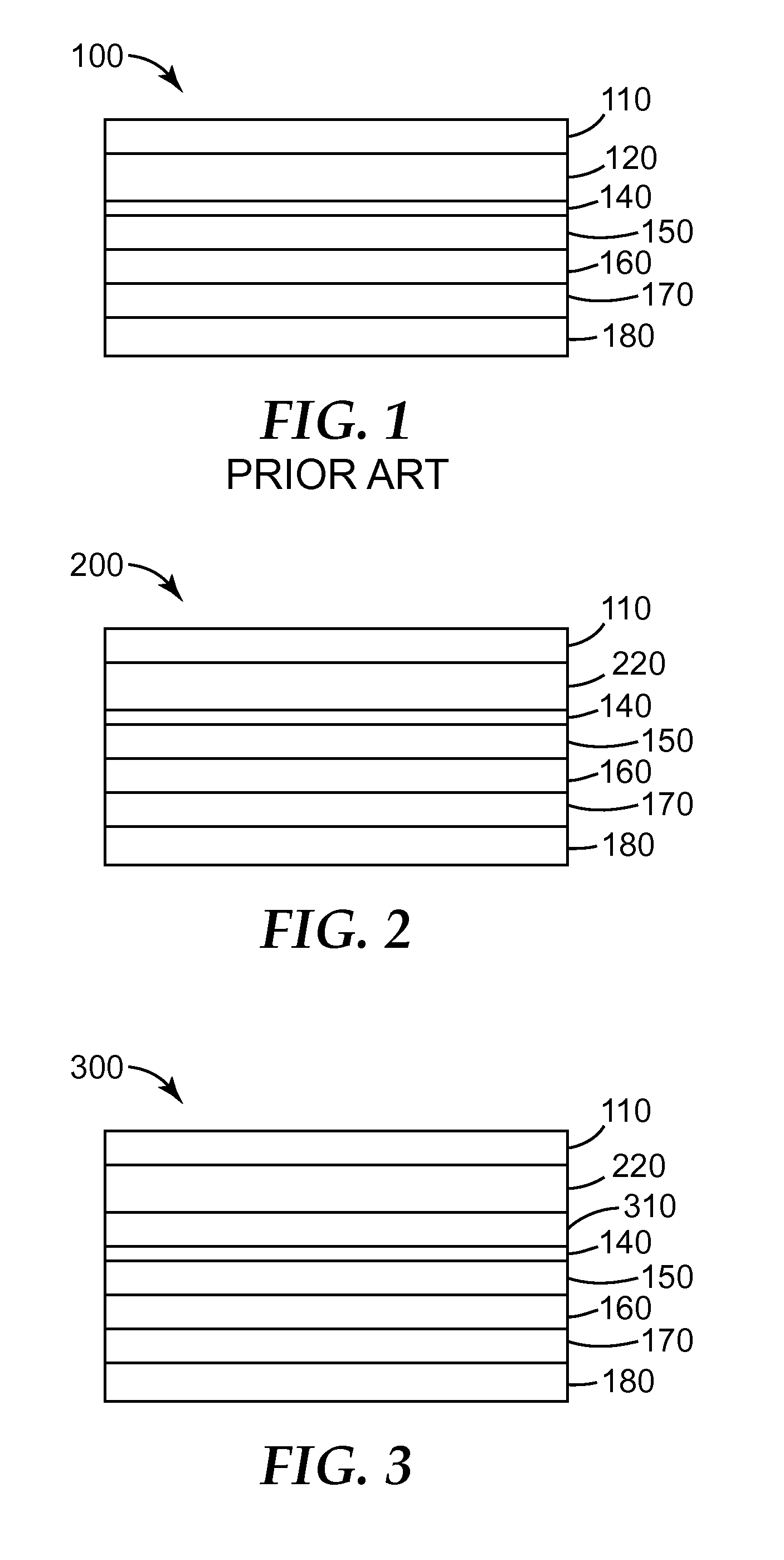
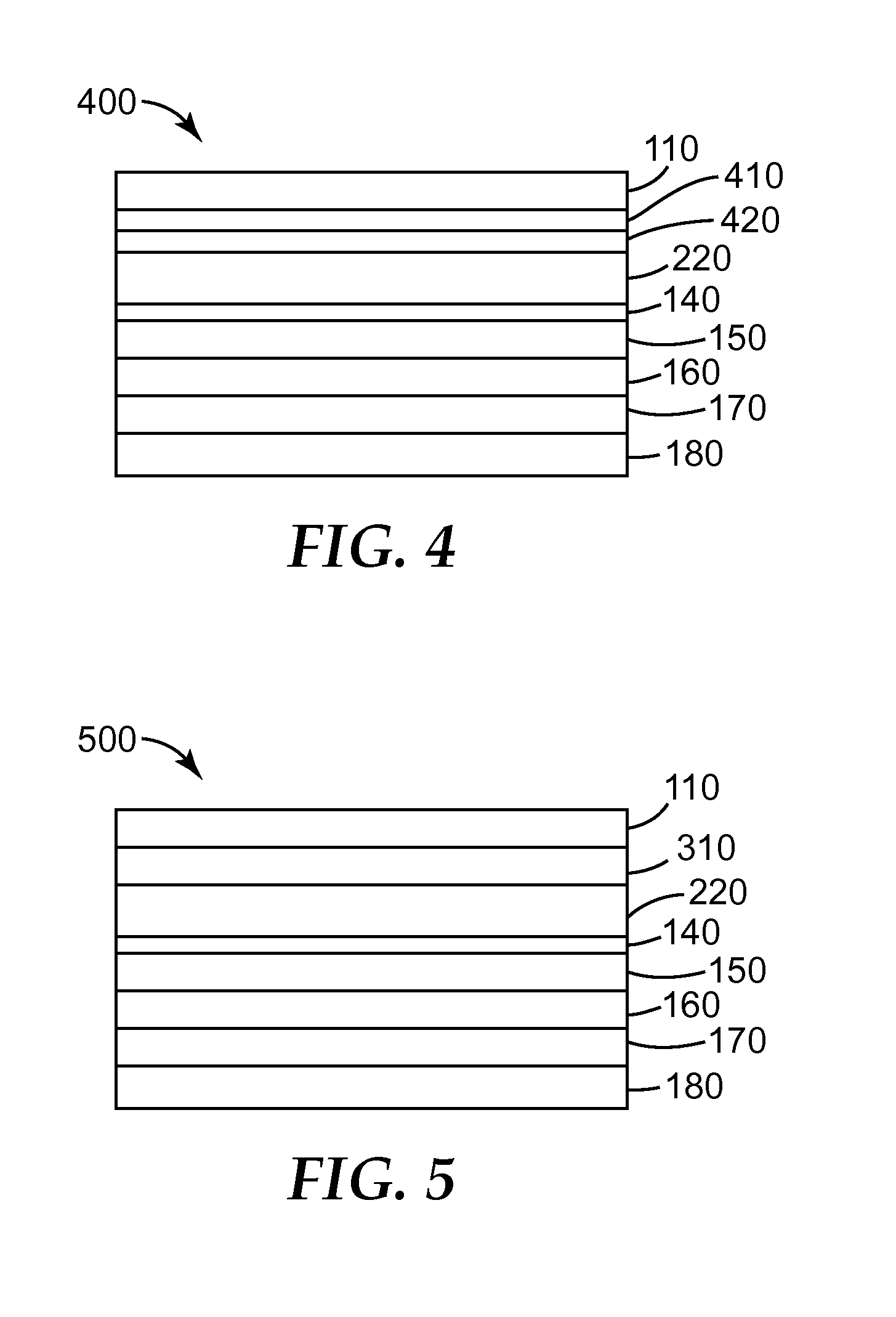
[0087]A multilayer optical film was prepared as following: a multilayer optical stack (described below) was prepared by coextruding first and second polymer layers through a multilayer polymer melt manifold to create a multilayer melt stream having five-hundred and fifty alternating layers. Two skin layers each having a thickness of approximately 4 microns were also co-extruded as protective layers on each side of the optical layer stack. The multilayer melt stream was cast onto a chilled roll creating a multilayer cast web. The multilayer cast web was then heated in a tenter oven to a temperature of about 105° C. prior to being biaxially oriented to a draw ratio of 3.8 by 3.8. A silver reflective layer approximately 100 nm thick was vapor deposited onto the film substrate. A copper layer approximately 80 nm thick was coated onto the silver layer. A 25 micron acrylic adhesive was coated onto the copper layer. The resulting multilayer optical film was bonded to an epoxy coated alumin...

example 2

[0091]A multilayer optical film was prepared as following: a multilayer optical stack (described below) was prepared by coextruding first and second polymer layers through a multilayer polymer melt manifold to create a multilayer melt stream having one hundred and fifty alternating layers. Two skin layers each having a thickness of approximately 4 microns were also co-extruded as protective layers on each side of the optical layer stack. The multilayer melt stream was cast onto a chilled roll creating a multilayer cast web. The multilayer cast web was then heated in a tenter oven to a temperature of about 105° C. prior to being biaxially oriented to a draw ratio of 3.8 by 3.8. A silver reflective layer approximately 100 nm thick can be vapor deposited onto the film substrate. A copper layer approximately 80 nm thick can be coated onto the silver layer. A 25 micron acrylic adhesive can be coated onto the copper layer. The resulting multilayer optical film can be bonded to an epoxy co...


PUM

PropertyMeasurementUnit
Nanoscale particle sizeaaaaaaaaaa
Relative humidityaaaaaaaaaa

Abstract

The present disclosure generally relates to durable solar mirror films, methods of making durable solar mirror films, and constructions including durable solar mirror films. In one embodiment, the present disclosure relates to a solar mirror film comprising: a multilayer optical film layer including having a coefficient of hygroscopic expansion of less than about 30 ppm per percent relative humidity; and a reflective layer having a coefficient of hygroscopic expansion.

Description

GOVERNMENT LICENSE RIGHTS[0001]The Government of the United States of America has rights in at least some of the inventions described in this Patent Application pursuant to DE-AC36-08G028308 (CRADA No. 08-316) awarded by the U.S. Department of Energy.TECHNICAL FIELD[0002]The present disclosure generally relates to durable solar mirror films, methods of making durable solar mirror films, and constructions including durable solar mirror films.BACKGROUND[0003]Renewable energy is energy derived from natural resources that can be replenished, such as sunlight, wind, rain, tides, and geothermal heat. The demand for renewable energy has grown substantially with advances in technology and increases in global population. Although fossil fuels provide for the vast majority of energy consumption today, these fuels are non-renewable. The global dependence on these fossil fuels has not only raised concerns about their depletion but also environmental concerns associated with emissions that resul...

Claims


Application Information

Patent Timeline
IPC IPC(8): G02B5/08G02B1/14F24S23/70
CPCG02B1/14G02B5/0808B32B33/00B32B2038/0092B32B2307/40B32B2038/0028B32B2037/246B32B37/153Y02E10/52F24S23/82Y02E10/40B32B5/00B32B7/02B32B7/12B32B15/08G02B5/08H01L31/042F24S23/70G02B1/10H02S40/22G02B5/0875
Inventor O'NEILL, MARK B.HENDERSON, ANDREW J.HEBRINK, TIMOTHY J.KATARE, RAJESH K.JING, NAIYONGNORTH, DIANEPETERSON, ERIC M.
Owner 3M INNOVATIVE PROPERTIES CO
Why Eureka
Try Eureka