
Liquid honing machine and liquid honing method

a honing machine and liquid technology, applied in the direction of edge grinding machines, manufacturing tools, transportation and packaging, etc., can solve the problems of affecting the efficiency of washing, affecting the quality of washing, and contaminating the washing zone, so as to prevent the occurrence of scratches, prevent the occurrence of washing defects of raw pipes for photoconductive drum substrate pipes, and prevent the effect of scratches

Inactive Publication Date: 2006-06-15
SHOWA DENKO KK
View PDF3 Cites 0 Cited by
  • Summary
  • Abstract
  • Description
  • Claims
  • Application Information

AI Technical Summary

Benefits of technology

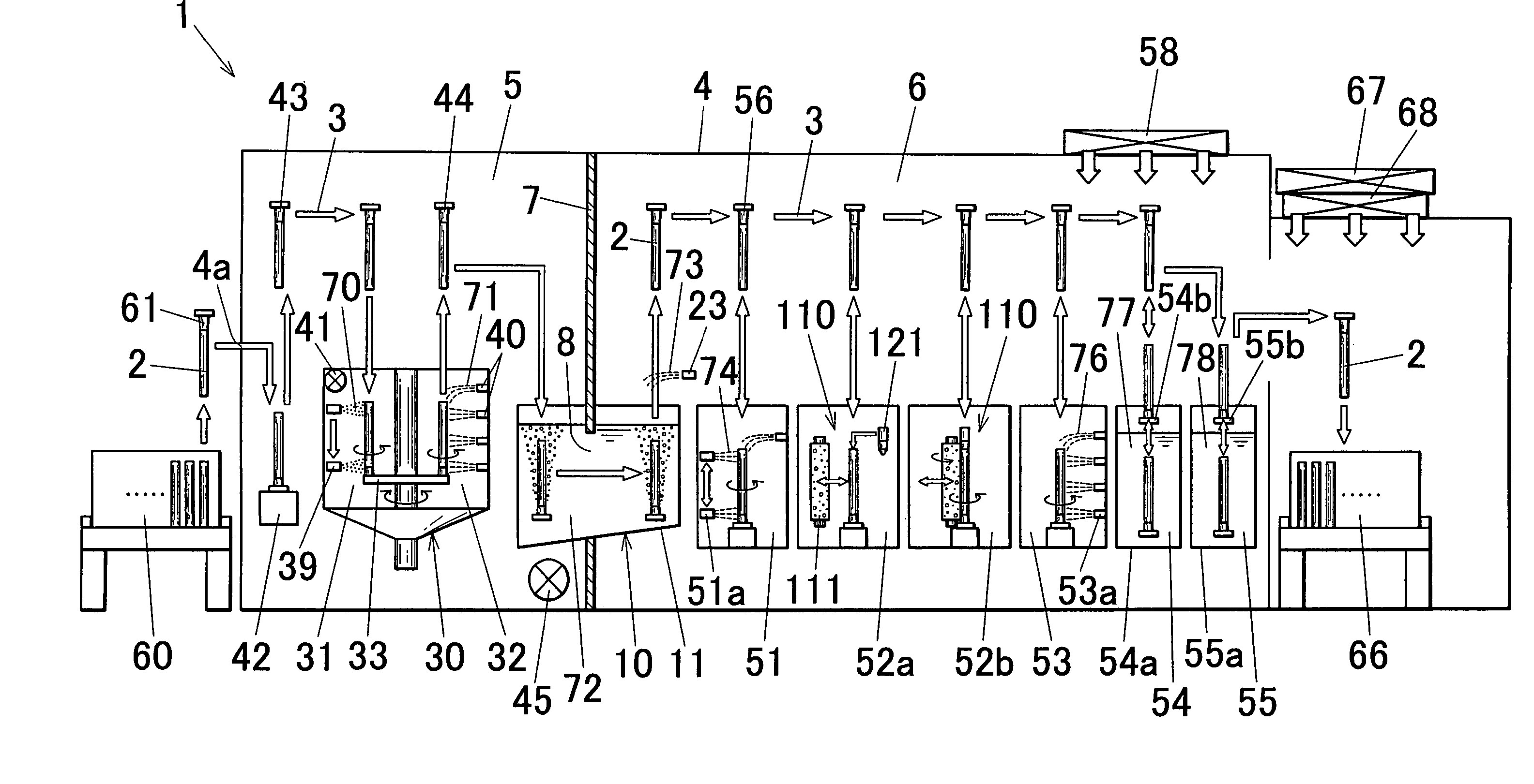
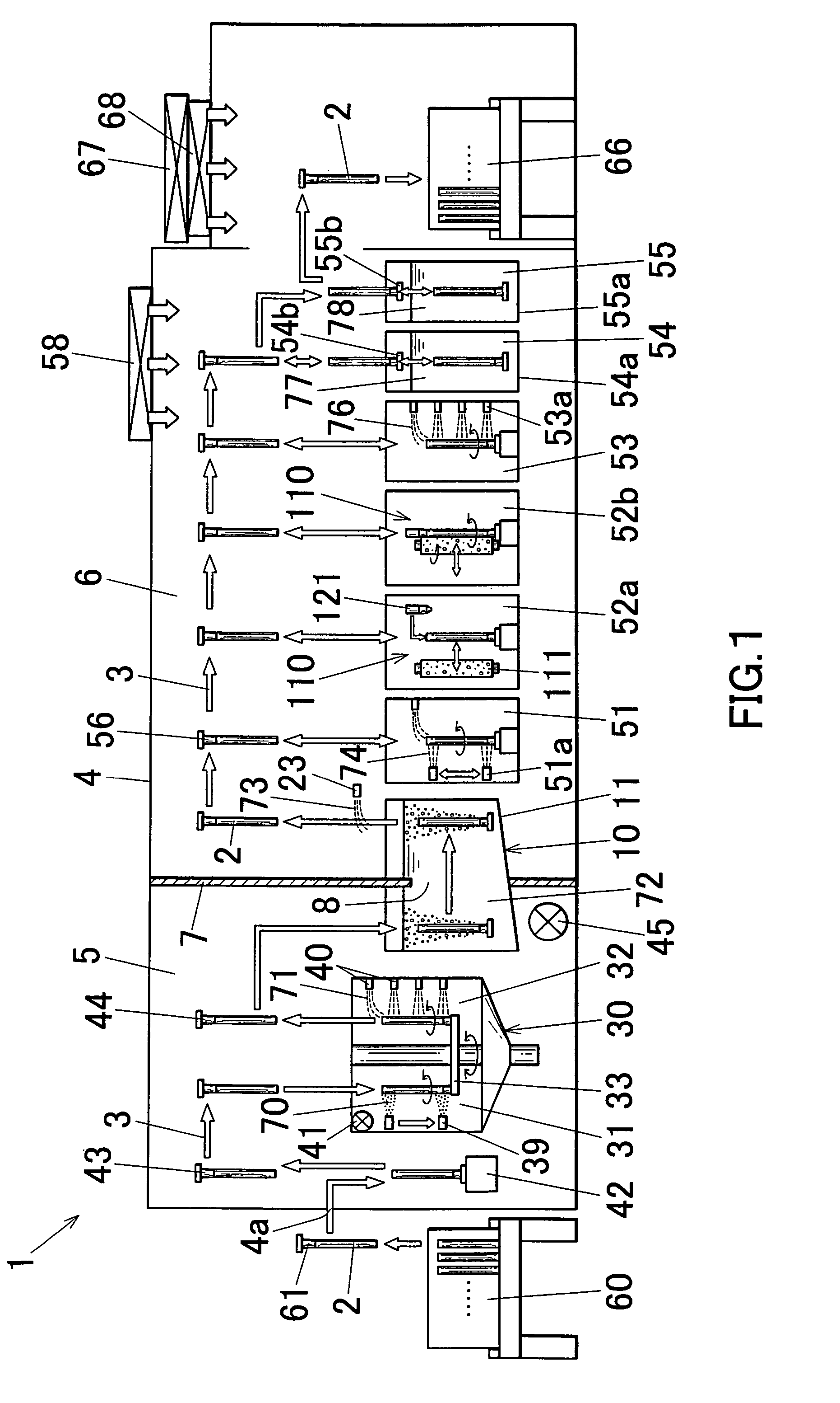
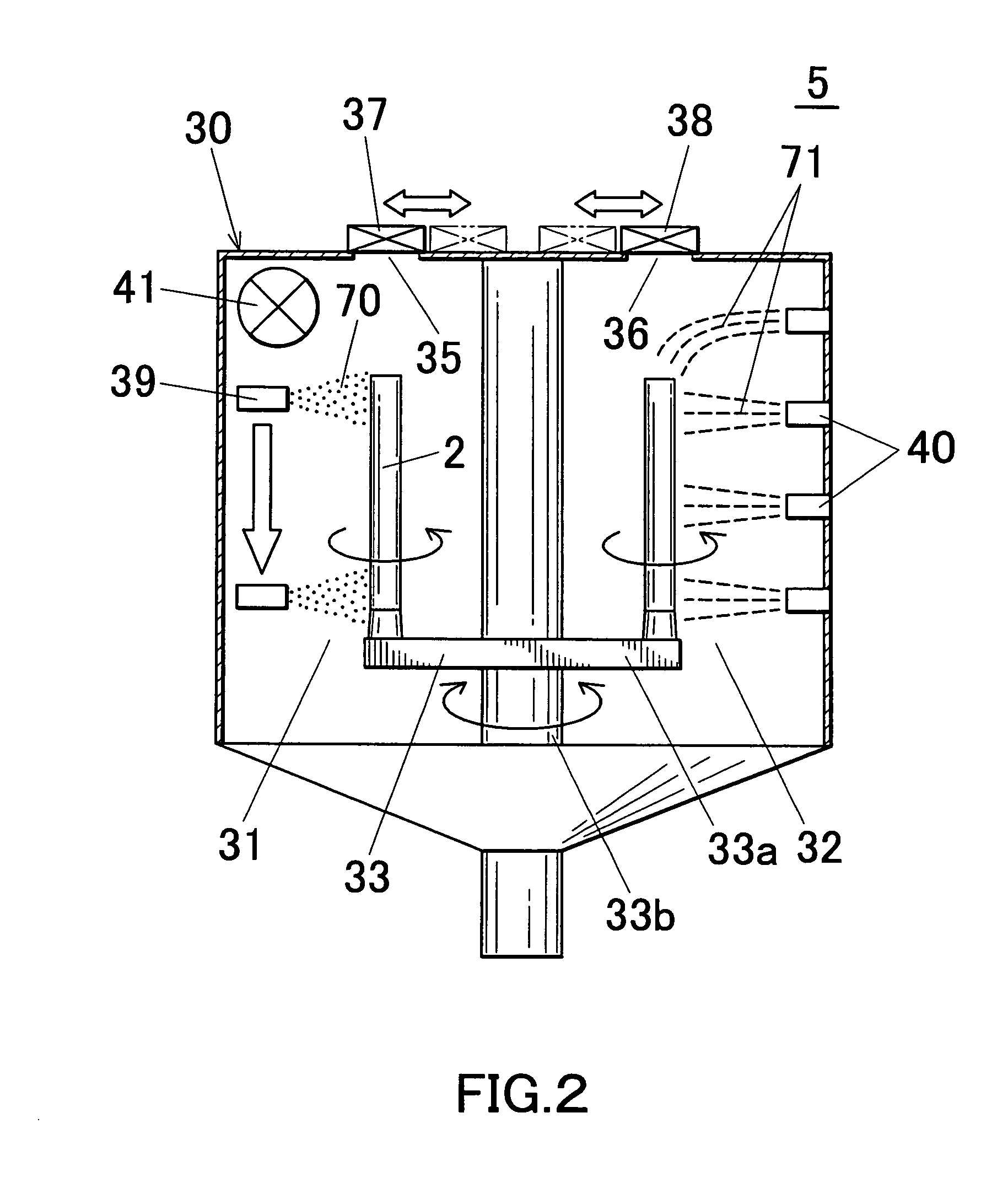
[0111] Since the partition wall is provided between the honing zone and the washing zone in the housing, it becomes possible to prevent foreign substances such as abrasive grains or dust flowing in the ambient gas in the honing zone from entering into the washing zone by the partition wall. Thus, contamination of the washing zone due to the entering of the foreign substances flowing in the ambient gas within the honing zone into the washing zone can be prevented.
[0161] According to the invention as recited in the aforementioned Item [63]-[68], the same effect as recited in the aforementioned Items [30]-[35] of the present invention can be attained.

Problems solved by technology

However, such liquid honing machine has the following drawbacks.
Thus, there is a drawback that the foreign substances such as abrasive grains and / or dirt suspended in the ambient gas will be flowed into the washing zone together with the ambient gas to contaminate the washing zone.
The contamination of the washing zone causes deterioration of washing efficiency, and also causes adhesion of the flowed foreign substances to the surface of the work, resulting in poor washing.

Method used


Image

  • Liquid honing machine and liquid honing method
  • Liquid honing machine and liquid honing method
  • Liquid honing machine and liquid honing method

Examples


example 1

[0326] As works 2, 5,000 pieces of raw pipes for photoconductor drum pipes were prepared. Each work 2 (raw pipe) was an aluminum drawn round pipe with a length of 200 to 450 mm, an external diameter of 15 to 50 mm, and a thickness of 0.2 to 2 mm. Each work 2 was subjected to a liquid honing process with the liquid honing machine 1 of the aforementioned embodiment.

examples 2 to 16

[0333] As works 2, 5,000 pieces of raw pipes for photoconductor drum pipes were prepared. Each work 2 (raw pipe) was an aluminum drawn round pipe with a length of 200 to 450 mm, an external diameter of 15 to 50 mm, and a thickness of 0.5 to 2 mm. Each work 2 was subjected to a liquid honing process with the liquid honing machine 1 of the aforementioned embodiment. Then, the rate of occurrence of defects due to scratches extending in the peripheral direction on the surface of the work 2 was examined. The results are shown in Table 1.

[0334] The scrubbing member 111 used in the scrub washing process among the liquid honing processes was a porous soft material with interconnected cells made of PVA foam whose 30% compressive stress was 8.8 kPa (90 gf / cm2), average cell diameter was 200 μm. The scrub washing was executed by setting the circumferential speed of the scrubbing member 111, the circumferential speed of the work 2, the contact width W of the surface of the scrubbing member 111...


PUM

PropertyMeasurementUnit
Angleaaaaaaaaaa
Speedaaaaaaaaaa
Speedaaaaaaaaaa

Abstract

A honing machine 1 is provided with a honing zone 5 for subjecting a work 2 to a liquid honing process and a washing zone 6 for subjecting the work 2 to which the liquid honing process was executed at the honing zone 5 to a washing process in a housing 4 shielded from an external air, the honing zone 5 and the washing zone 6 being disposed adjacently. A partition wall 7 for preventing an ambient gas of the honing zone 5 from entering into the washing zone 6 is disposed between the honing zone 5 and the washing zone 6 in the housing 4. An in-liquid conveying apparatus 10 for conveying the work 2 to which the liquid honing process was executed at the honing zone 5 from the honing zone 5 to the washing zone 6 with the work kept immersed in the liquid 72 in a carrying bath 11 is disposed in the housing 4.

Description

[0001] This application claims priority to Japanese Patent Applications No. 2004-319299 filed on Nov. 2, 2004, U.S. Provisional Application No. 60 / 625,983 filed on Nov. 9, 2004 and Japanese Patent Applications No. 2004-296757 filed on Oct. 8, 2004, the entire disclosures of which are incorporated herein by reference in their entireties. CROSS REFERENCE TO RELATED APPLICATIONS [0002] This application is an application filed under 35 U.S.C. §111(a) claiming the benefit pursuant to 35 U.S.C. §119(e)(1) of the filing date of U.S. Provisional Application No. 60 / 625,983 filed on Nov. 9, 2004, pursuant to 35 U.S.C. §111(b).FIELD OF THE INVENTION [0003] The present invention relates to a liquid honing machine and a liquid honing method for subjecting various works such as raw pipes for precision pipes or raw pipes for photoconductor drum substrate pipes to a liquid honing process. BACKGROUND ART [0004] A photoconductor drum substrate for use in a photoconductor drum to be mounted in an elec...

Claims


Application Information

Patent Timeline
IPC IPC(8): B24C1/00
CPCB24C3/02B24C3/085Y10T428/12993B24C11/005B24C3/12
Inventor HISATA, NOBUHIKO
Owner SHOWA DENKO KK
Learn More