
Portable rescue device and a method for locating such a device

a rescue device and portability technology, applied in the field of portability rescue devices, can solve the problems of life-threatening to victims, and difficult to see or hear victims, and achieve the effect of reducing the margin of error

Inactive Publication Date: 2006-06-15
CARLE FREDRIK
View PDF6 Cites 30 Cited by
  • Summary
  • Abstract
  • Description
  • Claims
  • Application Information

AI Technical Summary

Benefits of technology

[0004] It is an object of the present invention to provide a rescue device and a method of locating a rescue device that eliminates the above-mentioned drawbacks of the prior art and provides for substantially decreased margins of error.
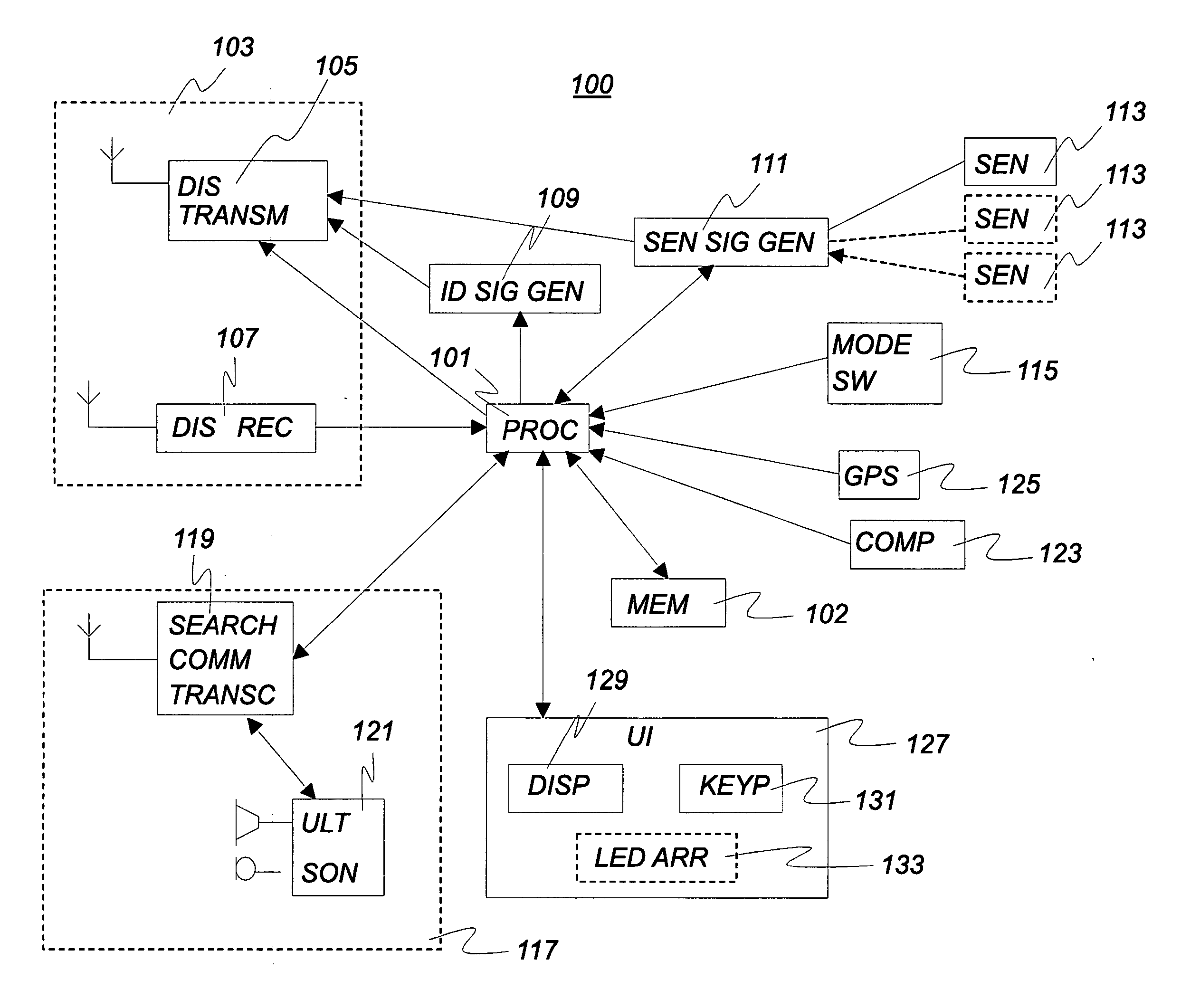
[0009] In an embodiment of the portable rescue device according to this invention, it comprises a second communication unit, arranged to communicate with another rescue device set in the search mode. This opens a lot of possibilities for cooperation between devices, which can further shorten the time it takes to find a victim.
[0014] In a further embodiment of the portable rescue device according to this invention the environmental data is carried by the distress signal. It is advantageous to only have to use one transmitter to transmit a lot of individual information in addition to the basic signal used by a searching device to perform the very detection of a victim.
[0015] In a further embodiment of the portable rescue device according to this invention the processor has a temporary disabling capability, wherein the portable rescue device, when in distress mode, at the reception of a disable signal is disabled and then automatically enabled again after a preset time. This is advantageous in that the searching rescue device is allowed to turn off all but one distress signal transmitter, as defined below in an embodiment of the method according to this invention, in order to easier find the one that is left. Additionally, the transmitting devices are saving power during the silent time period.
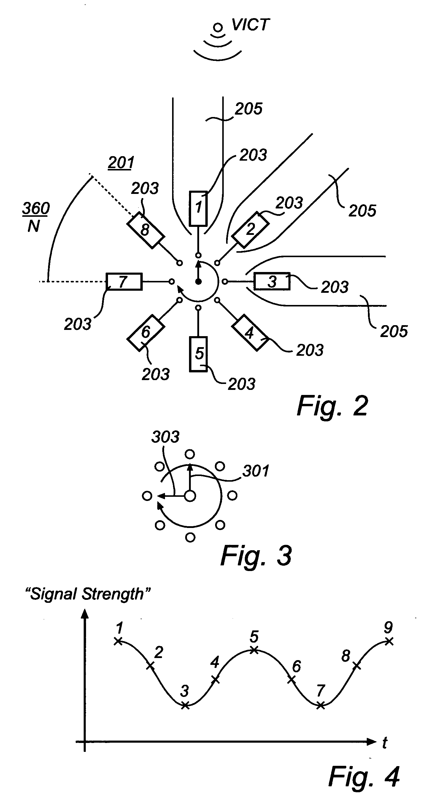
[0016] In a further embodiment of the portable rescue device according to this invention, wherein said multiple antennas are at least eight antennas, which are symmetrically distributed around a circle at equidistant angles. This provides an antenna structure having very good directional properties.
[0027] automatically grouping said rescue devices in at least two groups, and automatically distributing said several distress signals among said at least two groups. These steps are performed by a device that is set in the search mode. In this way several devices cooperates in order to divide the searching devices into groups, divide the victims into groups, and dedicate each search group to one of the victims group. Of course, when the search groups have started to find the victims they can be rearranged in the same way. Thereby the efficiency of the rescue operation is substantially increased.

Problems solved by technology

When persons, such as skiers, hikers, mountaineers, hunters, snowmobilers, military personnel, etc., are moving around in nature there is risk, in particular during winter and spring, of accidents.
In particular avalanches pose a life-threat to these persons.
Often, and in particular in case of an avalanche, the victims cannot be seen or heard or are very difficult to see or hear.
The rescue operation is often time critical.
The prior art solution provides rather wide margins of error both as regards the angle of direction towards the victim and as regards the distance to the victim.

Method used


Image

  • Portable rescue device and a method for locating such a device
  • Portable rescue device and a method for locating such a device
  • Portable rescue device and a method for locating such a device

Examples


Embodiment Construction

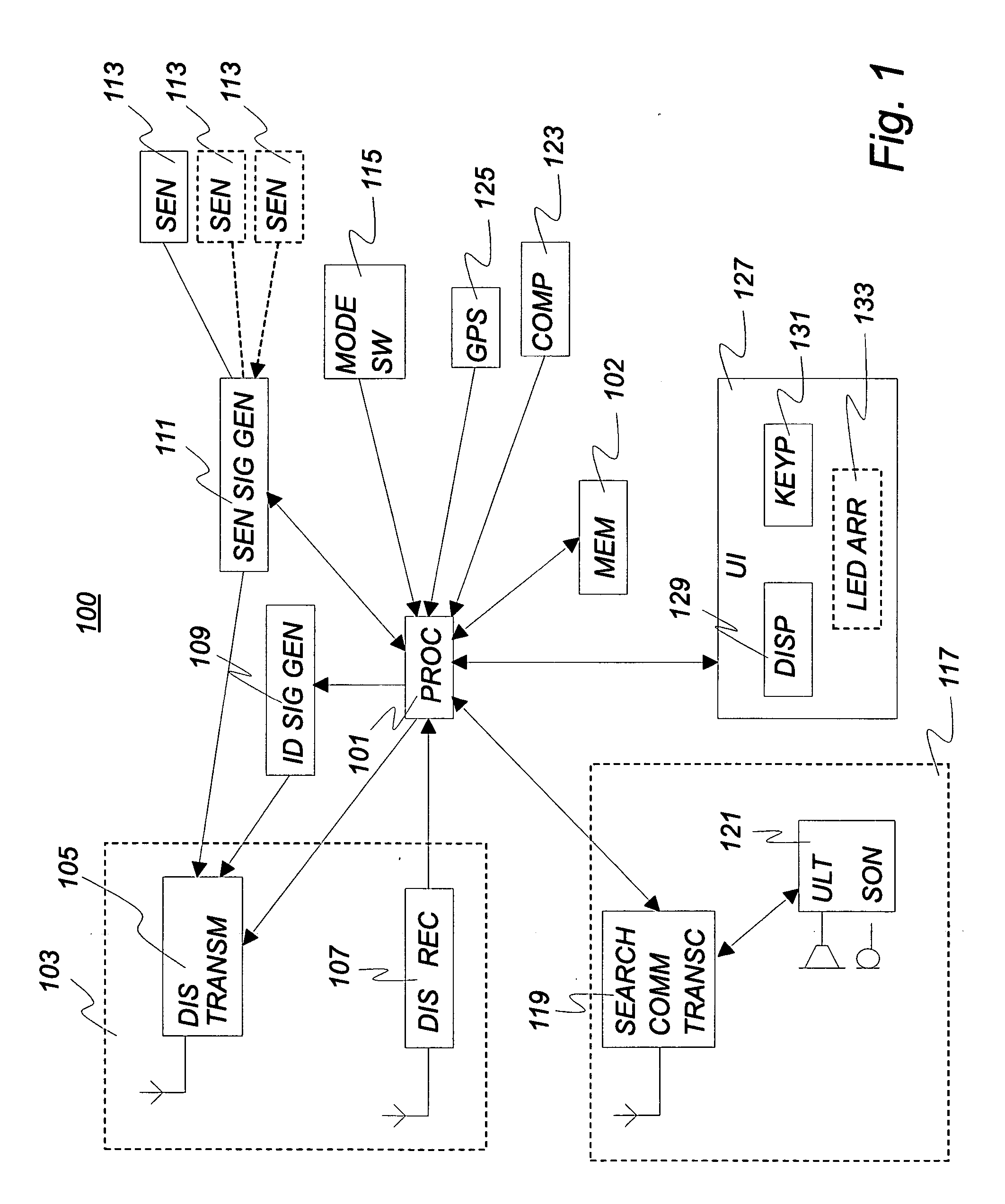
[0037] Referring to FIG. 1 a block diagram of an embodiment of the portable rescue device 100 is shown. The device 100 is meant to be carried by a user when she / he is moving around in the wilderness, as exemplified above in conjunction with the description of background of the invention. The device 100 has a processor 101, such as a microprocessor or a CPU, that is central for providing an amount of intelligence to the device. A first communication unit 103, shown as a dashed box, is connected to the processor for handling the transmission and reception of distress signals. The first communication unit 103 includes a distress transmitter 105 including a first antenna for transmitting, more particularly broadcasting, a distress signal from the device. It also includes a distress receiver 107 including a directional antenna structure, which is an assembly of several antennas. The antenna structure of this embodiment is shown in FIG. 2 and will be further described below. An identifica...


PUM


Abstract

A portable rescue device and a method for locating, by means of a first rescue device set in a search mode, a second rescue device set in a distress mode. In the method, a distress signal carrying a device identification is received from said second rescue device. A first bearing and a second bearing to the second rescue device are obtained. The first and second bearings are taken from a first and a second position, respectively. A distance between these positions is determined. A current distance and a current bearing to the second rescue device are determined on basis of the first and second bearings and the distance. The current bearing and the current distance are communicated to a user of the first rescue device. The portable rescue device is used for performing the method and for that purpose it includes a first communication unit for distress signal transmission and reception; a compass; a processor; a user interface; and a mode switch for switching between a search mode and a distress signal mode. The first communication device has an antenna structure that provides directional capability.

Description

FIELD OF THE INVENTION [0001] The present invention relates to a portable rescue device, which in particular is adapted to alpine use, and a method for locating, by means of a first rescue device set in a search mode, a second rescue device set in a distress mode. BACKGROUND OF THE INVENTION [0002] When persons, such as skiers, hikers, mountaineers, hunters, snowmobilers, military personnel, etc., are moving around in nature there is risk, in particular during winter and spring, of accidents. In particular avalanches pose a life-threat to these persons. Portable rescue devices are often used by these persons, in order to increase the chances for them to be found when an accident has occurred that stops them from moving on. Often, and in particular in case of an avalanche, the victims cannot be seen or heard or are very difficult to see or hear. Then the portable rescue device may save lives by providing an electronic location system, which is useful independently of visible sight. [...

Claims


Application Information

Patent Timeline
Patent Type & Authority Applications(United States)
IPC IPC(8): B63C9/00
CPCA62B33/00G01S5/0205G01S5/04G01S11/04G08B21/0272
Inventor CARLE, FREDRIKKOPTIOUG, ANDREI
Owner CARLE FREDRIK
Learn More