Monitoring system, apparatus to be monitored, monitoring apparatus, and monitoring method

Inactive Publication Date: 2006-06-15
FUJITSU LTD
View PDF15 Cites 8 Cited by
  • Summary
  • Abstract
  • Description
  • Claims
  • Application Information

AI Technical Summary

Benefits of technology

[0018] As described above, according to the invention, first information as event information of an event which occurs in the apparatus to be monitored is transmitted to the monitoring apparatus by the connectionless communication method, and second information as the event information is transmitted to the monitoring apparatus by a communication method different from the connectionless communication method. Therefore, even if the first information transmitted by the connectionless communication method is lost, the second information transmitted by a communication method different from the connectionless communication method can be reliably received by the monitoring apparatus. Thus, the monitoring appar

Problems solved by technology

However, the SNMP trap is sent by a connectionless communication method conformed with a UDP (User Datagram Protocol) and a communication path is not established prior to communication.
Consequently, there is the possibility that the SNMP trap is lost on the communication path (on the network) or on the monitoring apparatus side, and the monitoring apparatus cannot recognize the notification of the event from the apparatus to be monitored.
The SNMP trap is characterized in that, since it is transmitted by communication conformed with the UDP as a connectionless communication method, the SNMP trap can be realized with a relatively simple mechanism and notification can be sent at high speed but, on the other h

Method used


Image

  • Monitoring system, apparatus to be monitored, monitoring apparatus, and monitoring method
  • Monitoring system, apparatus to be monitored, monitoring apparatus, and monitoring method
  • Monitoring system, apparatus to be monitored, monitoring apparatus, and monitoring method

Examples


Embodiment Construction

[0024] Embodiments of the invention will be described hereinbelow with reference to the drawings.

1. Embodiment of the Invention

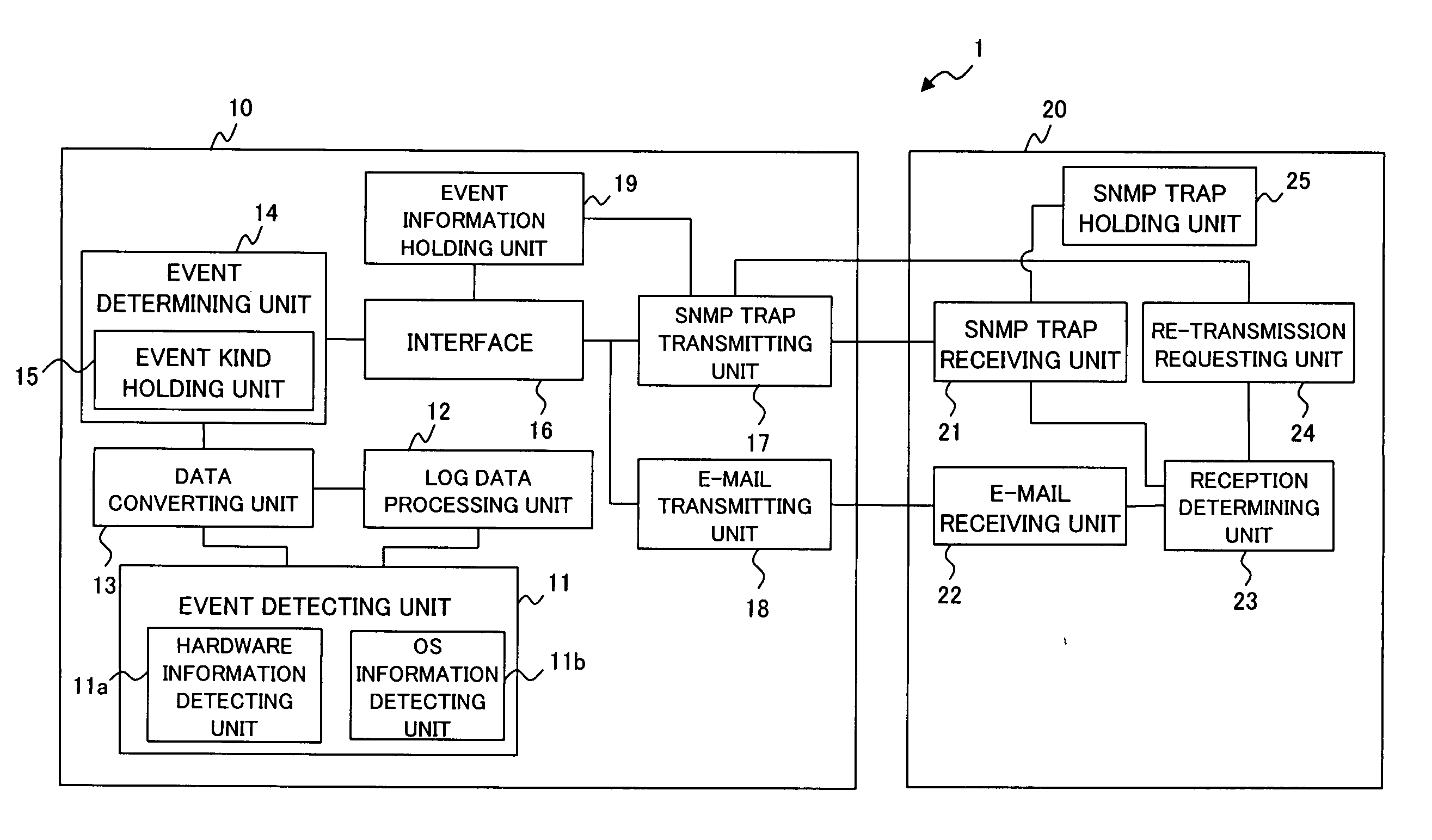
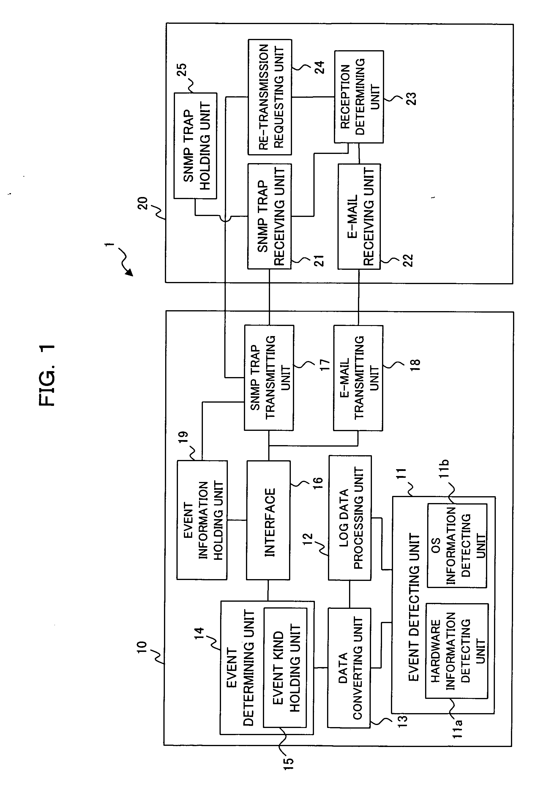
[0025] First, a configuration of a monitoring system 1 as an embodiment of the invention will be described with reference to the block diagram of FIG. 1. As shown in FIG. 1, the monitoring system 1 is constructed by an apparatus (agent) 10 to be monitored as an object of monitoring and a monitoring apparatus (manager) 20 for monitoring the apparatus 10 to be monitored.

[0026] The apparatus 10 to be monitored is, for example, a server. The apparatus 10 to be monitored and the monitoring apparatus 20 are connected to each other via a network such as a LAN (Local Area Network).

[0027] The apparatus 10 to be monitored includes an event detecting unit 11, a log data processing unit 12, a data converting unit 13, an event determining unit (event filter unit) 14, an interface 16, an SNMP (Simple Network Management Protocol) trap transmitting unit (first transmit...


PUM


Abstract

The present invention is directed to enable a monitoring apparatus to reliably obtain information of an event which occurs in an apparatus to be monitored in a monitoring system employing a connectionless communication method. An apparatus to be monitored comprises: a first transmitting unit for transmitting first information as event information related to an event in the apparatus to be monitored to a monitoring apparatus by a connectionless communication method; and a second transmitting unit for transmitting second information as the event information to the monitoring apparatus by a communication method different from the connectionless communication method. The monitoring apparatus comprises: a first receiving unit for receiving the first information transmitted from the first transmitting unit; and a second receiving unit for receiving the second information transmitted from the second transmitting unit.

Description

BACKGROUND OF THE INVENTION [0001] 1) Field of the Invention [0002] The present invention relates to a technique of monitoring an apparatus to be monitored in a monitoring system using a connectionless communication method (for example, a server system or a network system using an SNMP (Simple Network Management Protocol) trap). [0003] 2) Description of the Related Art [0004] Hitherto, in a monitoring (management) system in a server system, a network system, or the like, the SNMP (Simple Network Management Protocol) as a network monitoring (management) protocol employing a connectionless communication method is widely mounted and used. [0005] The monitoring system using the SNMP is constructed by, for example, an apparatus to be monitored and a monitoring apparatus which are connected to each other via a network. At the time of occurrence of an event in the apparatus to be monitored, by transmitting an SNMP trap as event information from the apparatus to be monitored to the monitori...

Claims


Application Information

Patent Timeline
IPC IPC(8): G06F15/173
CPCH04L41/0213H04L41/0677H04L41/069H04L43/0817H04L43/0847H04L41/34F16K1/228F16K1/42F16K25/005
Inventor MINEGISHI, AKIRA
Owner FUJITSU LTD
Why Eureka
Try Eureka