Method and control for testing air filter condition in HVAC system

a technology of air filter and condition, which is applied in the direction of domestic cooling equipment, instruments, and failure to burn, etc., can solve the problem of air filter clogging

Inactive Publication Date: 2006-06-22
CARRIER CORP
View PDF3 Cites 86 Cited by
  • Summary
  • Abstract
  • Description
  • Claims
  • Application Information

AI Technical Summary

Benefits of technology

[0005] A method and control is disclosed for utilizing this conc

Problems solved by technology

Over time, the air filter can become clogged.
One downside with this method is that often the periodic mainten

Method used


Image

  • Method and control for testing air filter condition in HVAC system
  • Method and control for testing air filter condition in HVAC system
  • Method and control for testing air filter condition in HVAC system

Examples


Embodiment Construction

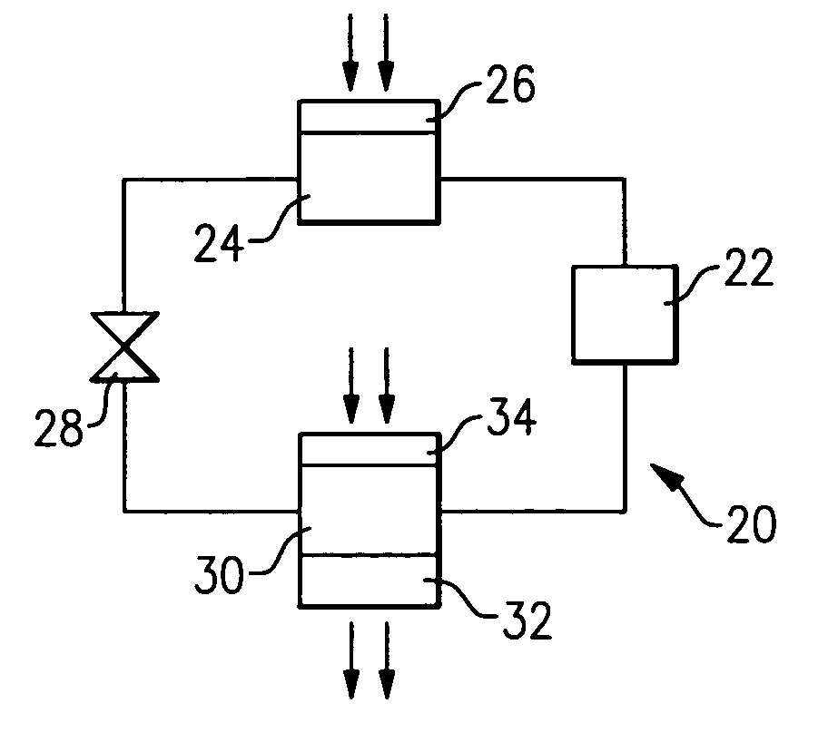
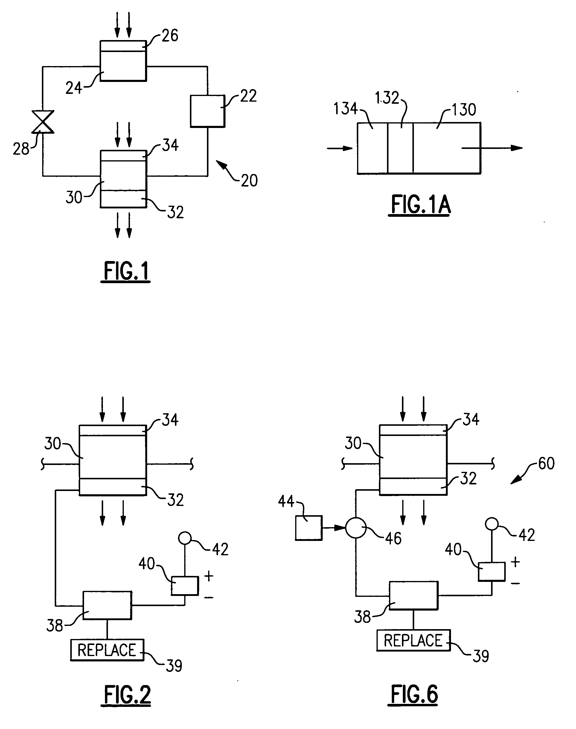
[0017]FIG. 1 shows a refrigerant system 20 incorporating a compressor 22 delivering a refrigerant to an outdoor heat exchanger 24. A fan 26 delivers air over the heat exchanger 24. Downstream of the heat exchanger 24, the refrigerant passes through an expansion device 28, and then moves to an indoor heat exchanger 30. While the present invention may be utilized in a heat pump that may either heat or cool an environment, the simple schematic of FIG. 1 shows an air conditioner for cooling the environment. By including a four-way valve for routing refrigerant from the compressor to either the outdoor heat exchanger 24, or to the indoor heat exchanger 30, both heating and cooling can be selectively achieved as known. In the simple embodiment shown in FIG. 1, the refrigerant cycle 20 is a cooling cycle, such as an air conditioner.

[0018] In FIG. 1, a fan 32 pulls air through an air filter 34, and over the heat exchanger 30. As shown in FIG. 1A, the fan 32 pulls air through an air filter ...


PUM


Abstract

A method and control for determining an air filter condition in an HVAC system forces a change in a motor speed for a fan for driving air through the air filter and into an environment to be conditioned. When the motor speed is changed, an expected change in temperature in the environment is monitored. If the actual change is not as expected, a determination may be made that the air filter is clogged.

Description

BACKGROUND OF THE INVENTION [0001] This application relates to a method and control for testing the condition of an air filter, and identifying when the air filter should be replaced based upon forcing a change in one system condition, and then monitoring a corresponding change in another condition indicative of the condition of the air filter. [0002] Heating, ventilation and air conditioning systems (HVAC) typically include a fan driving air over a heat exchanger, and into an environment to be conditioned. The heat exchanger could be an evaporator to cool the air, a portion of a furnace, or a condenser in a heat pump to heat the air. In all such systems, the air flowing into the environment typically passes through an air filter. Over time, the air filter can become clogged. Various ways have been developed for identifying when the air filter is clogged and should be replaced. Traditionally, a routine maintenance has been recommended in which the air filter would be replaced on som...

Claims


Application Information

Patent Timeline
IPC IPC(8): F01P7/04F25B49/00G01K13/00F25D17/00F24F8/10
CPCB60H1/00828B60H3/06B60H2003/0683F23N2031/26F24F3/1603F24F11/0079F24F11/0086Y02B30/746F24F11/30F24F11/77F23N2231/26Y02B30/70F24F8/10F24F11/39
Inventor KANG, PENGJURADCLIFF, THOMAS D.FARZAD, MOHSENFINN, ALAN M.
Owner CARRIER CORP
Why Eureka
Try Eureka