
Anchor arm for seismic logging tool

a technology of anchoring arm and seismic logging, which is applied in the direction of instruments, surveying, and well accessories, etc., can solve the problems of weakpoint mechanism breaking, force to be exerted on the first end of the anchoring arm, force to be exerted on the weakpoint mechanism, etc., and achieve the effect of increasing the cam radius

Active Publication Date: 2006-06-22
SCHLUMBERGER TECH CORP
View PDF11 Cites 21 Cited by
  • Summary
  • Abstract
  • Description
  • Claims
  • Application Information

AI Technical Summary

Benefits of technology

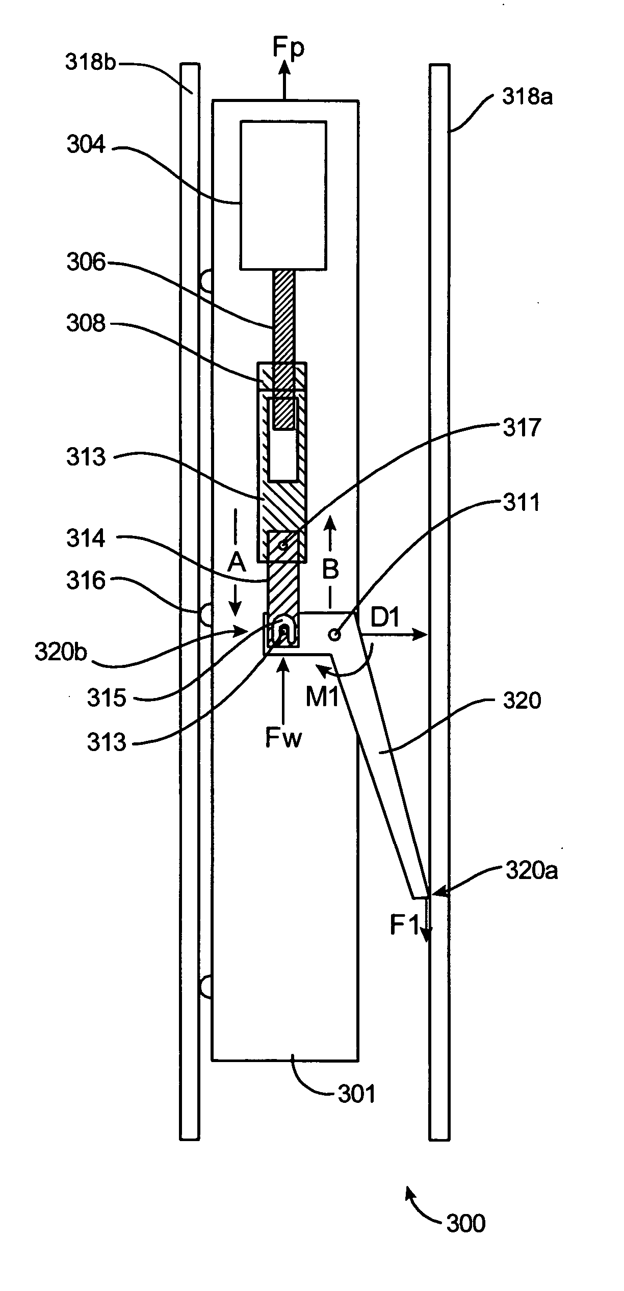
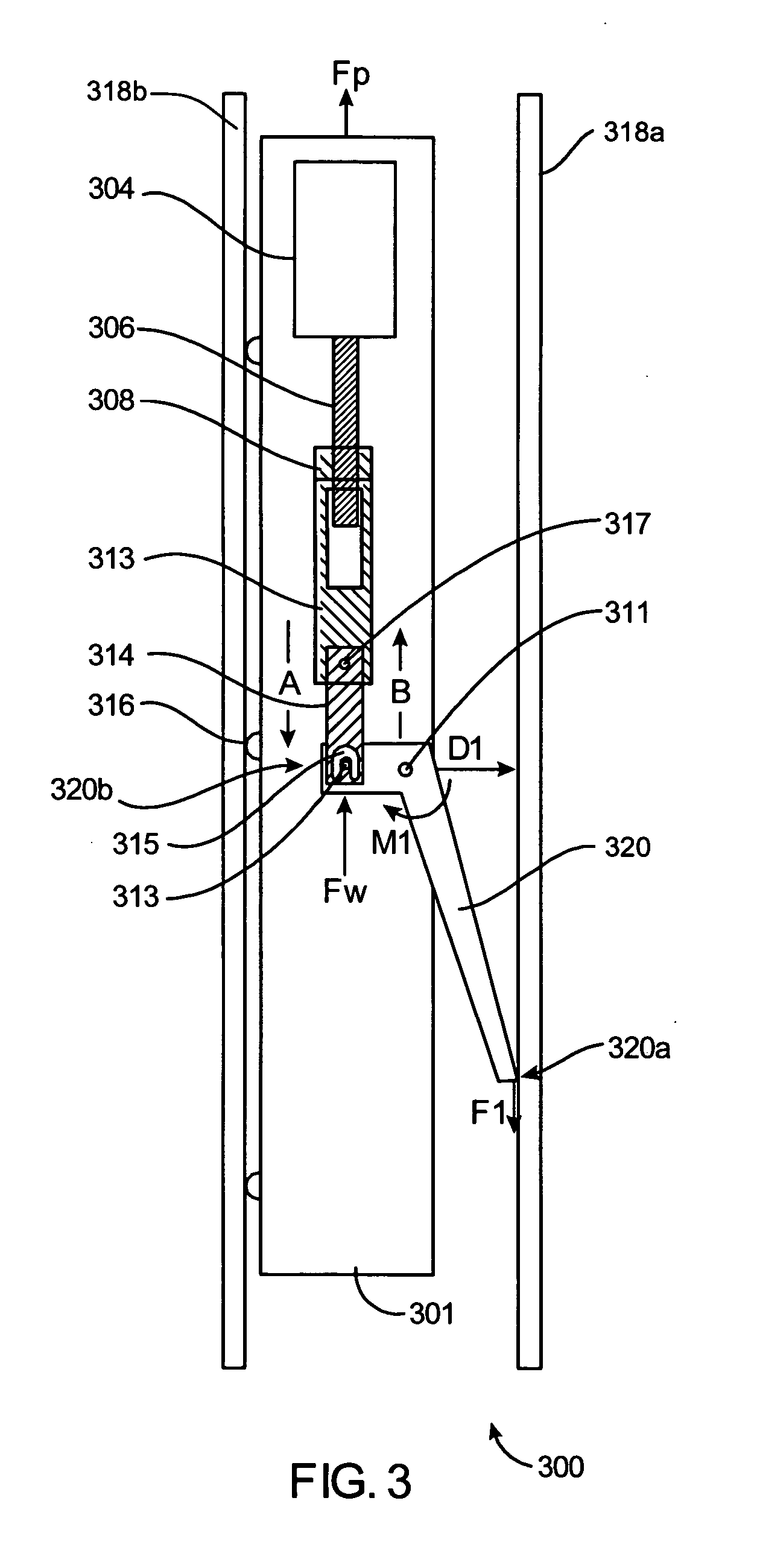
[0008] Various aspects of the present invention are directed to an anchoring arm for use with a borehole seismic acquisition tool which includes a tool body. The anchoring arm includes a first end adapted for contacting a borehole wall surface. The first end includes a tip portion which defines a slot. The anchoring arm also includes a movable cam inserted into the slot and removably secured to the first end via a first connector pin inserted through an aperture in the cam. According to at least one implementation, the cam is at least partially rotatable about the first connector pin. In one embodiment, the cam is designed to rotate in a substantially elliptical motion about the first connector pin. In this way, the radius of the cam may increase as the cam is rotated about the first connector pin. Further, according to at least one embodiment, when the cam is placed in contact with the surface of a borehole wall, rotation of the cam against the borehole wall surface may cause a displacement of the first end of the anchoring arm away from the borehole wall surface, thereby causing a force to be exerted upon the first end of the anchoring arm.
[0009] An alternate embodiment of the present invention is directed to a borehole seismic acquisition tool. The tool includes a tool body having at least one sensor package, an anchoring arm, and anchoring arm linkage adapted to connect the anchoring arm to the tool body. The anchoring arm linkage includes a weakpoint mechanism adapted to break in response to a minimum threshold amount of breaking force being applied to the weakpoint mechanism. The anchoring arm includes a first end and a second end, the second end being pivotally attached to the anchoring arm linkage, and the first end being adapted for contacting a surface of the borehole wall. According to at least one implementation, the first end of the anchoring arm includes a tip portion which defines a slot. The anchoring arm also includes a movable cam inserted into the slot and removably secured to the first end via a first connector pin inserted through an aperture in the cam. According to at least one implementation, the cam is at least partially rotatable about the first connector pin. In one embodiment, the cam is designed to rotate in a substantially elliptical motion about the first connector pin. In this way, the radius of the cam may increase as the cam is rotated about the first connector pin. Further, according to at least one embodiment, when the cam is placed in contact with the surface of a borehole wall, rotation of the cam against the borehole wall surface may cause a displacement of the first end of the anchoring arm away from the borehole wall surface, thereby causing a force to be exerted upon the weakpoint mechanism. In at lest one embodiment, the force exerted upon the weakpoint mechanism may be at least equal to the minimum threshold amount of breaking force.

Problems solved by technology

Further, according to at least one embodiment, when the cam is placed in contact with the surface of a borehole wall, rotation of the cam against the borehole wall surface may cause a displacement of the first end of the anchoring arm away from the borehole wall surface, thereby causing a force to be exerted upon the first end of the anchoring arm.
Further, according to at least one embodiment, when the cam is placed in contact with the surface of a borehole wall, rotation of the cam against the borehole wall surface may cause a displacement of the first end of the anchoring arm away from the borehole wall surface, thereby causing a force to be exerted upon the weakpoint mechanism.
The rotation of the cam against the borehole wall surface causes a force to be exerted upon the weakpoint mechanism, which, in turn, causes the weakpoint mechanism to break.
The breaking of the weakpoint mechanism results in a release of the borehole seismic acquisition tool from the stuck position.

Method used


Image

  • Anchor arm for seismic logging tool
  • Anchor arm for seismic logging tool
  • Anchor arm for seismic logging tool

Examples


Embodiment Construction

[0021] The present invention describes different techniques which may be used to improve multi-shuttle seismic array designs in order to provide improved seismic logging capabilities, performance, and reliability. One aspect of the present invention is directed to an improved anchor arm for a seismic logging tool such as, for example, a VSI shuttle.

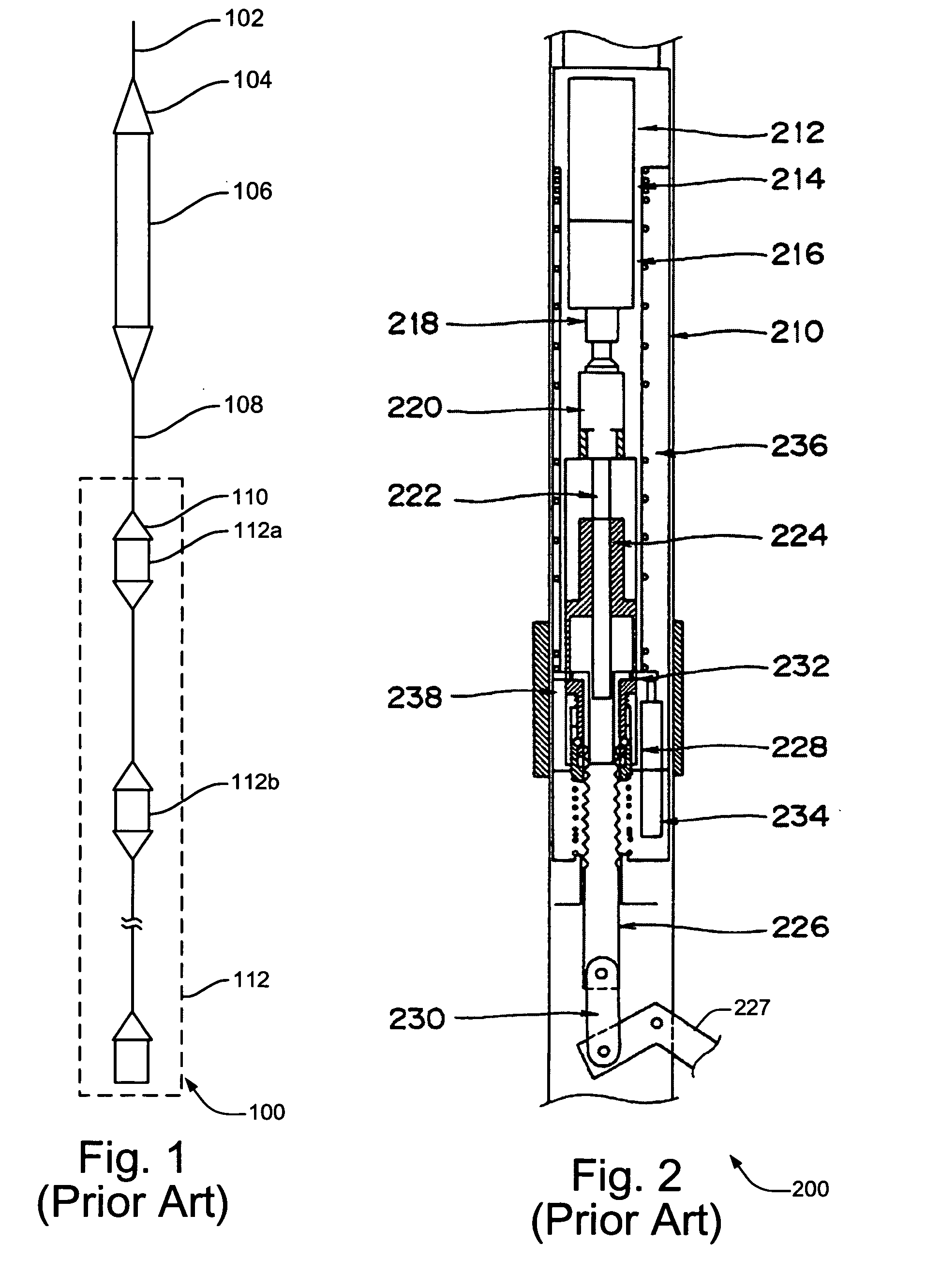
[0022]FIG. 3 shows a portion of VSI shuttle 300 which may be used for implementing various aspects of the present invention. In the example of FIG. 3, VSI shuttle portion 300 is shown to be anchored to a wall portion (318a, 318b) of a borehole using anchor arm 330. According to at least one embodiment, VSI shuttle portion 300 may be similar in design to the VSI shuttle 200 of FIG. 2. In the embodiment of FIG. 3, the anchoring mechanism for shuttle portion 300 includes gear drive motor 304, ball screw 306, ball nut 308, push rod 313, anchor arm linkage 314, pivoting anchor arm 320, standoff portions 316, etc.

[0023] It will be appreciated...


PUM


Abstract

A technique is described for releasing a borehole seismic acquisition tool from a stuck position within a borehole. The borehole seismic acquisition tool includes a tool body having at least one sensor package. The borehole seismic acquisition tool further includes an anchoring arm, and anchoring arm linkage adapted to connect the anchoring arm to the tool body. The anchoring arm linkage includes a weakpoint mechanism adapted to break in response to a minimum threshold amount of breaking force being applied upon the weakpoint mechanism. The anchoring arm includes a first end and a second end. The second end of the anchoring arm is pivotally attached to the anchoring arm linkage. The first end of the anchoring arm includes a tip portion which defines a slot. The anchoring arm also includes a movable cam inserted into the slot and removably secured to the first end via a first connector pin inserted through an aperture in the cam. According to at least one implementation, the cam is at least partially rotatable about the first connector pin. An exposed portion of the cam is engaged with the surface of borehole wall. When a failure of retraction of the anchoring arm is detected, the cam may be caused to rotate against the borehole wall surface in response. The rotation of the cam against the borehole wall surface causes a force to be exerted upon the weakpoint mechanism, which, in turn, causes the weakpoint mechanism to break. The breaking of the weakpoint mechanism results in a release of the borehole seismic acquisition tool from the stuck position. According to a specific embodiment, rotation of the cam against the borehole wall surface may be caused by a pulling force applied to a top portion of the borehole seismic acquisition tool.

Description

BACKGROUND OF THE INVENTION [0001] Seismic shuttle logging tools are generally known for use in performing vertical seismic profile (VSP) surveys from boreholes to evaluate the surrounding underground formations. An example of a multi-shuttle seismic array is illustrated in FIG. 1 of the drawings. As illustrated in FIG. 1, a multi-shuttle seismic array 100 may comprise a number of seismic logging tools linked together by means of a cable and logged through a borehole while seismic signals are generated at the surface. In the example of FIG. 1, the logging cable 102 (which may range in length, for example, from 4 to 46 km) connects to a logging head 104 which may include an Electrically Controlled Release Device (ECRD) and a Versatile Seismic Imager (VSI) cartridge 106. The multi-shuttle seismic array may also include a VSI interconnect cable 108, and a plurality of seismic logging shuttles 112 which may function as seismic receivers. At each measurement level, each shuttle is anchor...

Claims


Application Information

Patent Timeline
Patent Type & Authority Applications(United States)
IPC IPC(8): E21B47/00E21B47/01G01V1/52
CPCE21B23/01G01V11/005G01V1/52
Inventor KANAYAMA, KAZUMASAWILSON, COLINUNDERHILL, WILLIAM
Owner SCHLUMBERGER TECH CORP
Learn More