Micro column electron beam apparatus formed in low temperature co-fired ceramic substrate

a technology of electron beam and micro-column, which is applied in the direction of instruments, nuclear engineering, heat measurement, etc., can solve the problems of small signal delay and rc signal delay between interconnections

Inactive Publication Date: 2006-06-22
ELECTRONICS & TELECOMM RES INST +1
View PDF7 Cites 22 Cited by
  • Summary
  • Abstract
  • Description
  • Claims
  • Application Information

AI Technical Summary

Benefits of technology

[0010] The present invention provides a micro column electro beam apparatus having a reduced number of interconnections arranged on a substrate.

Problems solved by technology

As such, the interconnections have different resistances, and due to this resistance difference and the parasitic capacitance, an RC signal delay between the interconnections occurs.
As a result, due to the RC signal delay, different signals are applied to an electrode of each micro column to which the same signal should be applied.
Thus, a micro column electron beam apparatus having a small number of interconnections and a small signal delay is required.

Method used


Image

  • Micro column electron beam apparatus formed in low temperature co-fired ceramic substrate
  • Micro column electron beam apparatus formed in low temperature co-fired ceramic substrate
  • Micro column electron beam apparatus formed in low temperature co-fired ceramic substrate

Examples


Embodiment Construction

[0021] The present invention will now be described more fully with reference to the accompanying drawings, in which exemplary embodiments of the invention are shown. The invention may, however, be embodied in many different forms and should not be construed as being limited to the embodiments set forth herein; rather, these embodiments are provided so that this disclosure will be thorough and complete, and will fully convey the concept of the invention to those skilled in the art. In the drawings, the thicknesses of layers and regions are exaggerated for clarity. Like reference numerals in the drawings denote like elements.

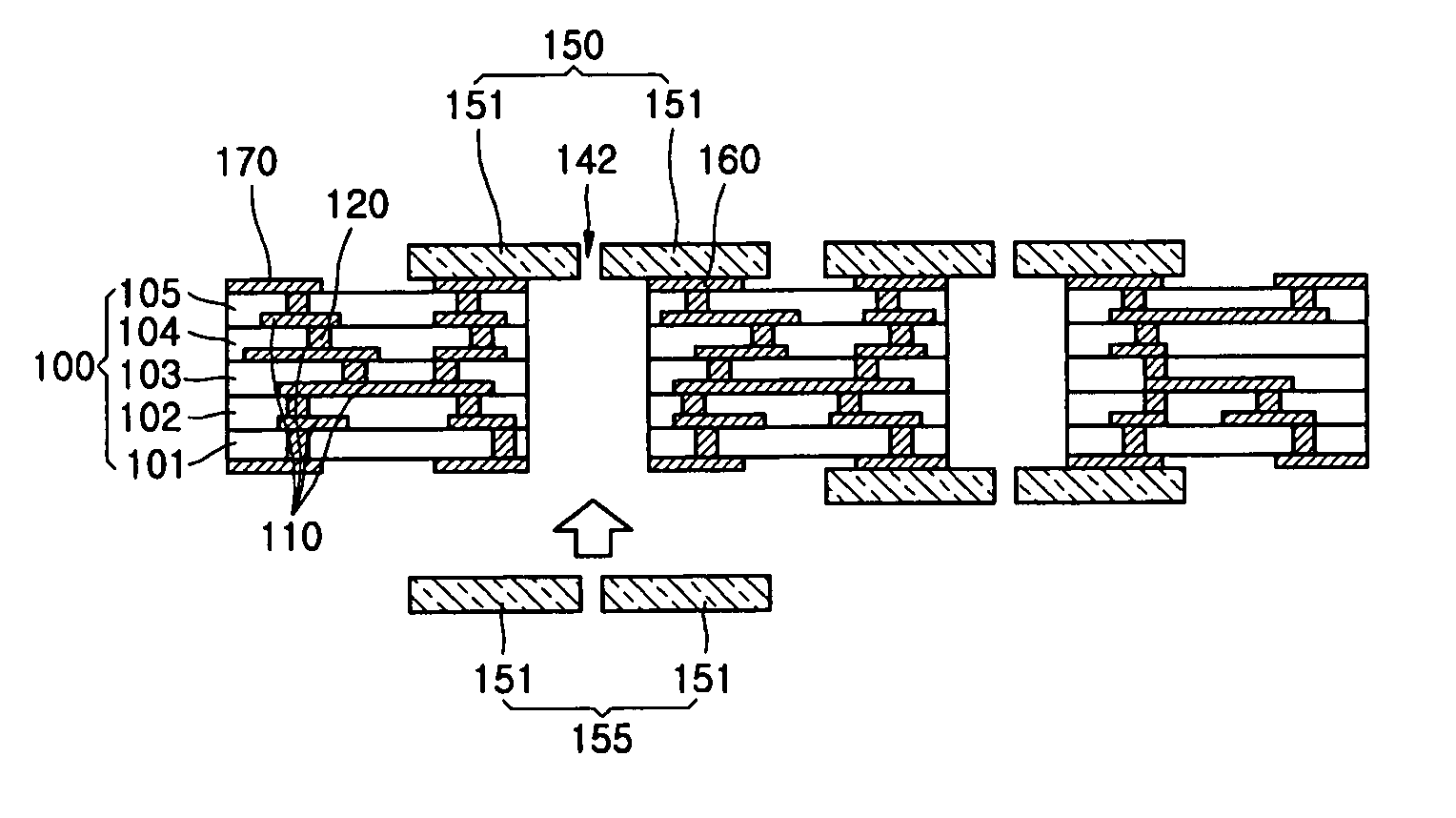
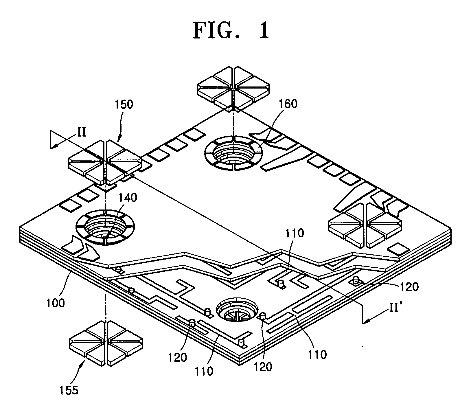
[0022]FIG. 1 is an exploded perspective view of a micro column electron beam apparatus according to an embodiment of the present invention, and FIG. 2 is a cross-sectional view of a low temperature co-fired ceramic (LTCC) substrate taken along line II-II′ of FIG. 1.

[0023] The micro column electron beam apparatus of FIG. 1 includes an LTCC substrate 100. The LTCC...


PUM


Abstract

A micro column electron beam apparatus having a reduced number of interconnections is provided. The micro column electron beam apparatus includes: a low temperature co-fired ceramic (LTCC) substrate; a plurality of deflector electrodes attached to a predetermined top portion of the LTCC substrate; a pad electrode placed at a top edge of the LTCC substrate and transmitting an external signal to the deflector electrodes; and a connection unit placed in the LTCC substrate and electrically connecting the deflector electrode and the pad electrode.

Description

CROSS-REFERENCE TO RELATED PATENT APPLICATIONS [0001] This application claims the benefit of Korean Patent Application Nos. 10-2004-0109003, filed on Dec. 20, 2004 and 10-2005-0049196, filed on Jun. 9, 2005 in the Korean Intellectual Property Office, the disclosures of which incorporated herein in their entirety by reference. BACKGROUND OF THE INVENTION [0002] 1. Field of the Invention [0003] The present invention relates to a micro column electron beam apparatus, and more particularly, to a micro column electron beam apparatus having a reduced number of interconnections. [0004] 2. Description of the Related Art [0005] In general, micro column electron beam apparatuses or micro columns are used for radiating electron beams generated by an electron emission source or a cathode source onto a wafer. Specifically, micro columns are used to form a photoresist pattern on a wafer by supplying electron beams thereon. [0006] Micro columns include an electron emission source or a cathode sour...

Claims


Application Information

Patent Timeline
Patent Type & Authority Applications(United States)
IPC IPC(8): H01L23/52
CPCB82Y10/00B82Y40/00H01J37/1477H01J37/3177H01J2237/03H01J2237/1205
Inventor KIM, DAE JUNJEONG, JIN WOOCHOI, SANG KUKKIM, DAE YONGKIM, HO SEOB
Owner ELECTRONICS & TELECOMM RES INST
Why Eureka
Try Eureka