Transverse Hydroelectric Generator

a generator and transverse technology, applied in the direction of electric generator control, machines/engines, mechanical equipment, etc., can solve the problems of life-threatening flooding downstream from the site of the hydraulic power plant infrastructure, displace all human inhabitants, etc., and achieve positive net energy and reduce environmental impact

Inactive Publication Date: 2006-06-22
INTEGRATED POWER TECH CORP
View PDF16 Cites 25 Cited by
  • Summary
  • Abstract
  • Description
  • Claims
  • Application Information

AI Technical Summary

Benefits of technology

[0011] Secondly, because adapting to change of both magnitude and direction of the streamlines of a free flowing motive fluid formed the basis of the guiding concepts of the present invention; this also avails the present invention the applicability to other bodies of water besides the ocean. Having been conceived for free flowing motive fluid use obviat...

Problems solved by technology

Presently the hydroelectric power plant industry earns revenues of approximately thirty billion dollars annually, but unfortunately is in a state of decline mainly due to the environmental and civic costs of implementing the existing technology.
Environmental impact of the prior art hydroelectric power plant threatens extinction to aquatic species living downstream from the proposed power plant infrastructure, and also displaces all human inhabitants that live in what would become the flood plane of the infrastructure.
Furthermore, given the prior art technology, there still exists the possibility of life threatening flooding occurring downstream from the site of the hydraulic power plant infrastructure.
Overall these costs have weighed heavily in civic planners' decisions in adopting hydroelectric power generation to the point of putting the industry in a state of such decline that leading companies involved in this business are contemplating other areas of endeavor.
Inherent problems in the prior implementation of hydroelectric power generation have exacerbated the present state of declining interest in this technology.
This requirement imposes on these systems almost exclusive implementation in freshwater systems with large sc...

Method used


Image

  • Transverse Hydroelectric Generator
  • Transverse Hydroelectric Generator
  • Transverse Hydroelectric Generator

Examples


Embodiment Construction

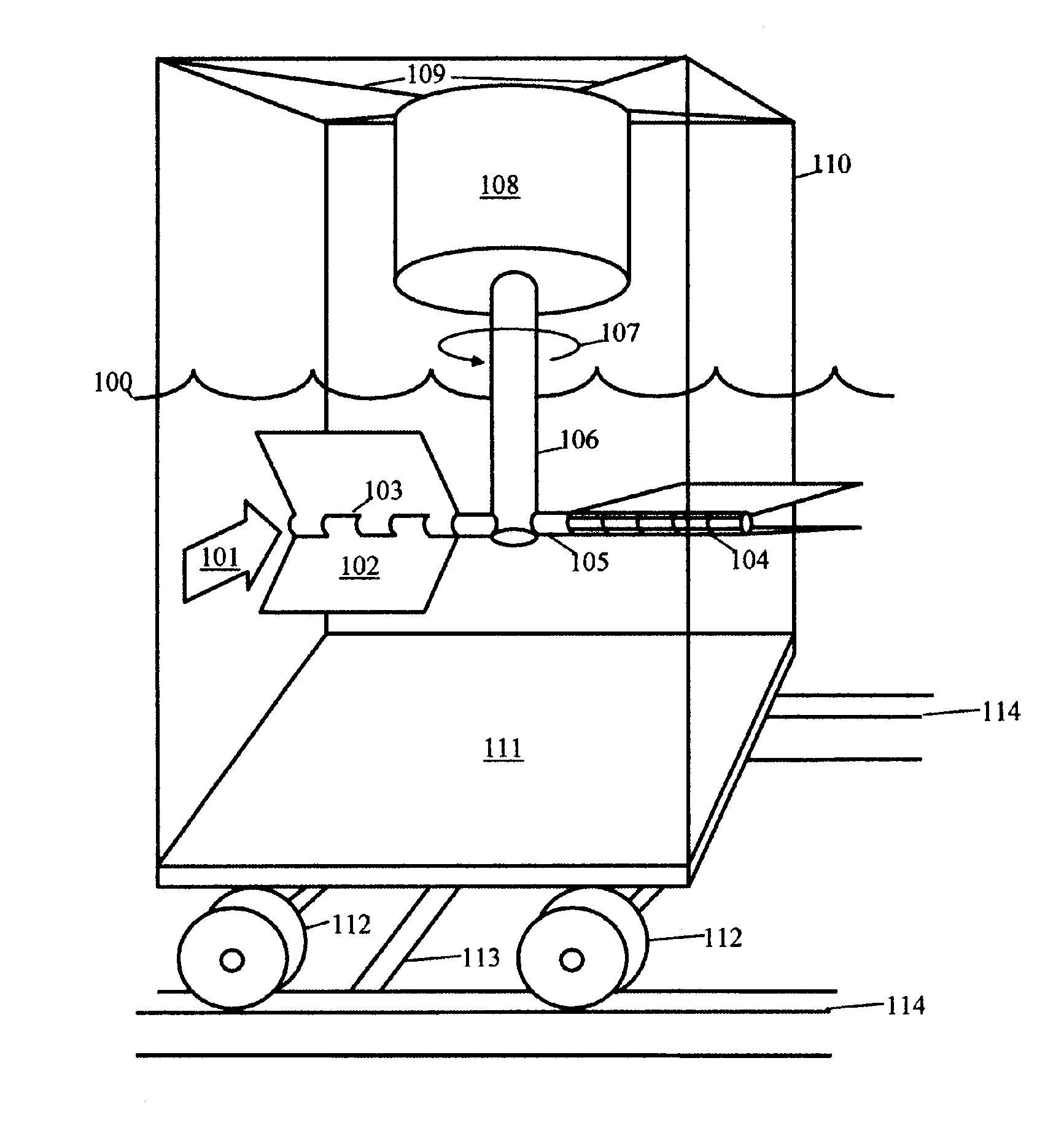
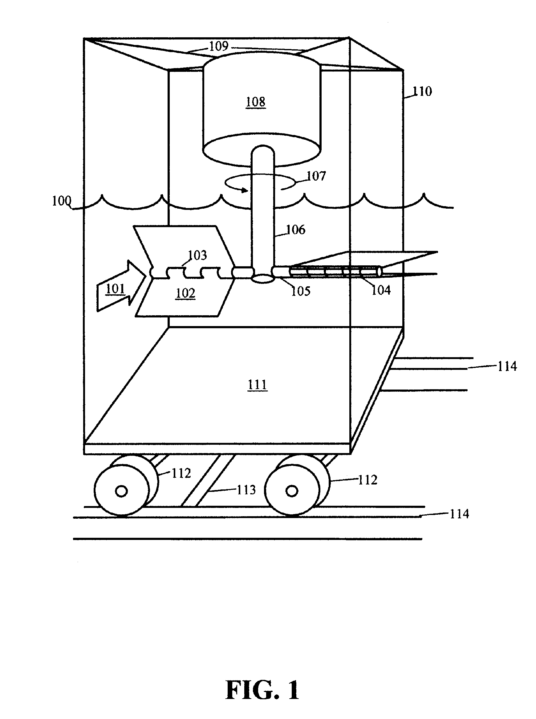
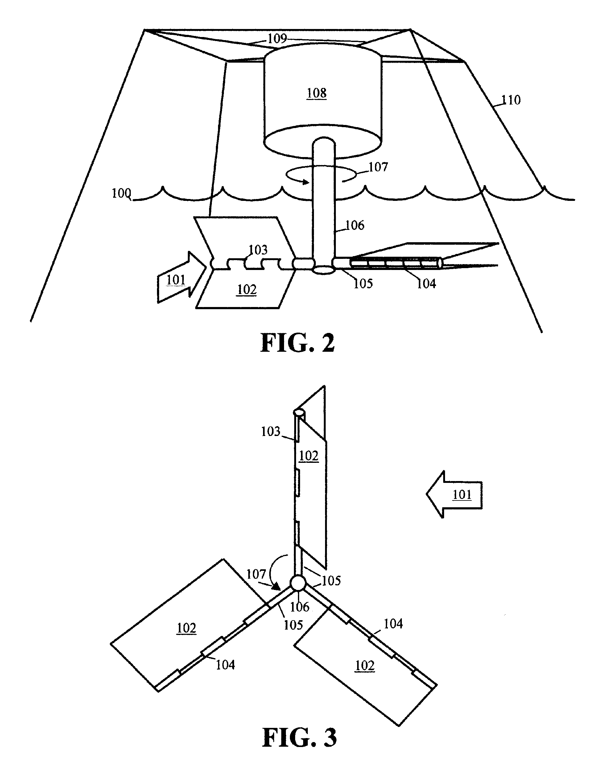
[0028] The present invention is directed to a transverse hydroelectric generator comprising hinged runner blades for adaptively extracting energy from a free flowing motive fluid that continuously changes direction and magnitude of flow. The following description contains specific information pertaining to various embodiments and implementations of the present invention. One skilled in the art will recognize that the present invention may be implemented in a manner different from that specifically depicted in the present specification. Furthermore, some of the specific details of the invention are not described in order to maintain brevity and to not obscure the invention. The specific details not described in the present specification are within the knowledge of a person of ordinary skills in the art. Obviously, some features of the present invention may be omitted or only partially implemented and remain well within the scope and spirit of the present invention.

[0029] The followi...


PUM


Abstract

A power plant extracts energy from a free flowing motive fluid by means of a transverse mounted generator with its rotor extending downward into the flow. Runner blades with hinges attain the greatest surface area when the flow is tangent to and in the same direction as the rotor rotation. The hinges fold the runner blades to minimize the surface area proportional to drag when the blades oppose the flow. The generator with feedback control charges batteries, produces hydrogen fuel by electrolysis of water, or further couples to a DC motor coupled to an AC generator. Other features optionally perform such tasks as adaptively locating the generator in the maximum velocity flow, controlling and communicating the state of charge of the battery, or gauging and controlling the electrolysis process and communicating the fullness of the hydrogen gas output tanks.

Description

BACKGROUND OF INVENTION [0001] 1. Field of the Invention [0002] The present invention is generally in the field of power plants. More specifically, the present invention is in the field of hydrokinetic generators with means to adapt to changes in streamline direction and magnitude of a free flowing motive fluid. [0003] 2. Description of Prior Art [0004] For over two thousand years mankind has known of harnessing the kinetic energy in flowing water to perform mechanical endeavors. In the past two hundred years the pace in which developments emerged in the practice of hydraulics has accelerated. The advent of the turbine in the first half of the nineteenth century culminated in the present advancements in hydroelectric generation, with this period of innovation and intense interest peaking in the first quarter of the twentieth century. Since then, fossil fuels have dominated as the high net energy, readily available energy source in the production of electricity and other conveyors of...

Claims


Application Information

Patent Timeline
IPC IPC(8): F03B13/00F03B13/10H02P9/04
CPCF03B17/065F05B2220/61F05B2240/94F05B2240/97Y02E10/28Y02E70/10Y02E60/36Y02E10/30Y02E10/20
Inventor GIZARA, ANDREW ROMAN
Owner INTEGRATED POWER TECH CORP
Why Eureka
Try Eureka