Interior rearview mirror system with compass

US20060132939A1Inactive Publication Date: 2006-06-22DONNELLY CORP

Image

  • Interior rearview mirror system with compass
  • Interior rearview mirror system with compass
  • Interior rearview mirror system with compass

Examples


Embodiment Construction

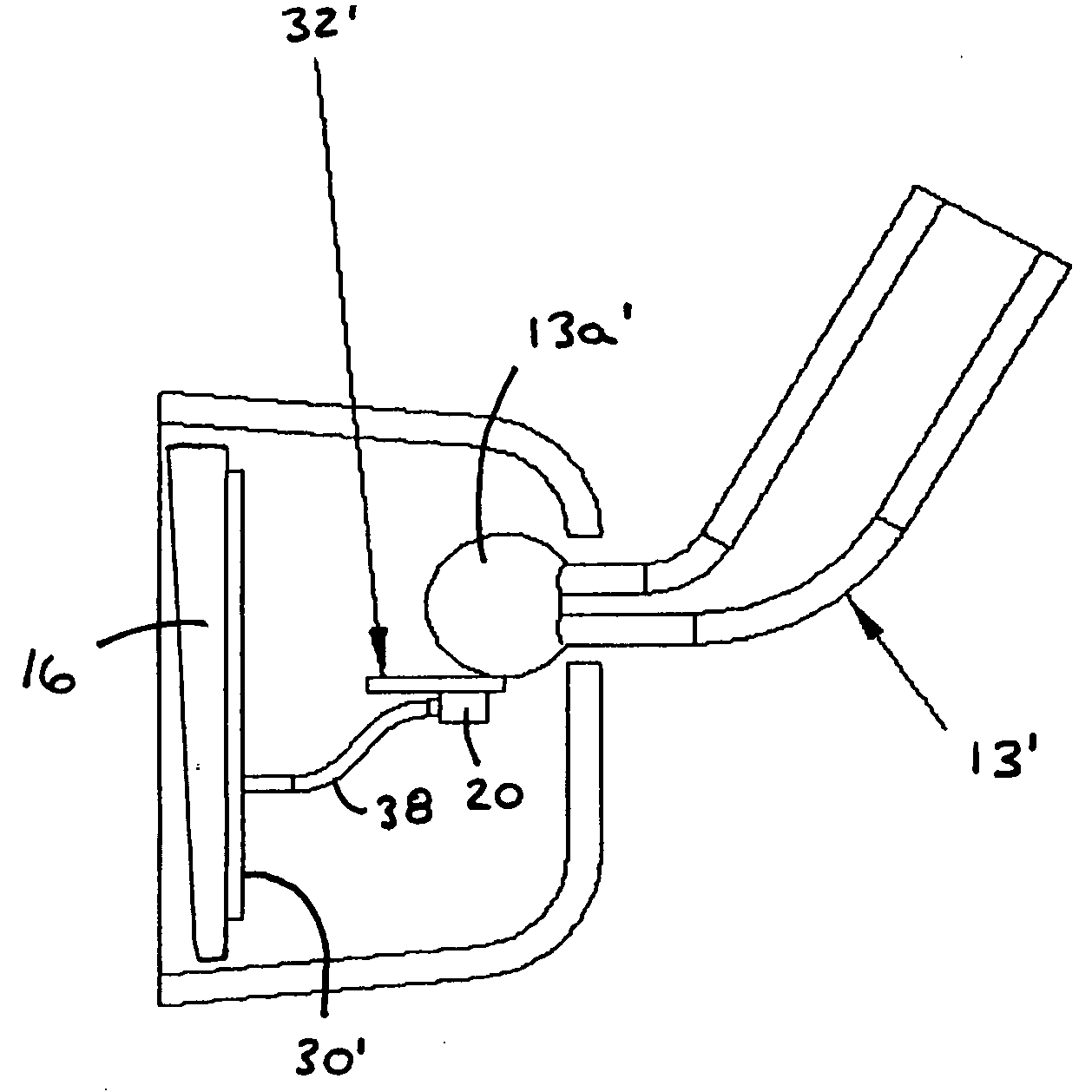
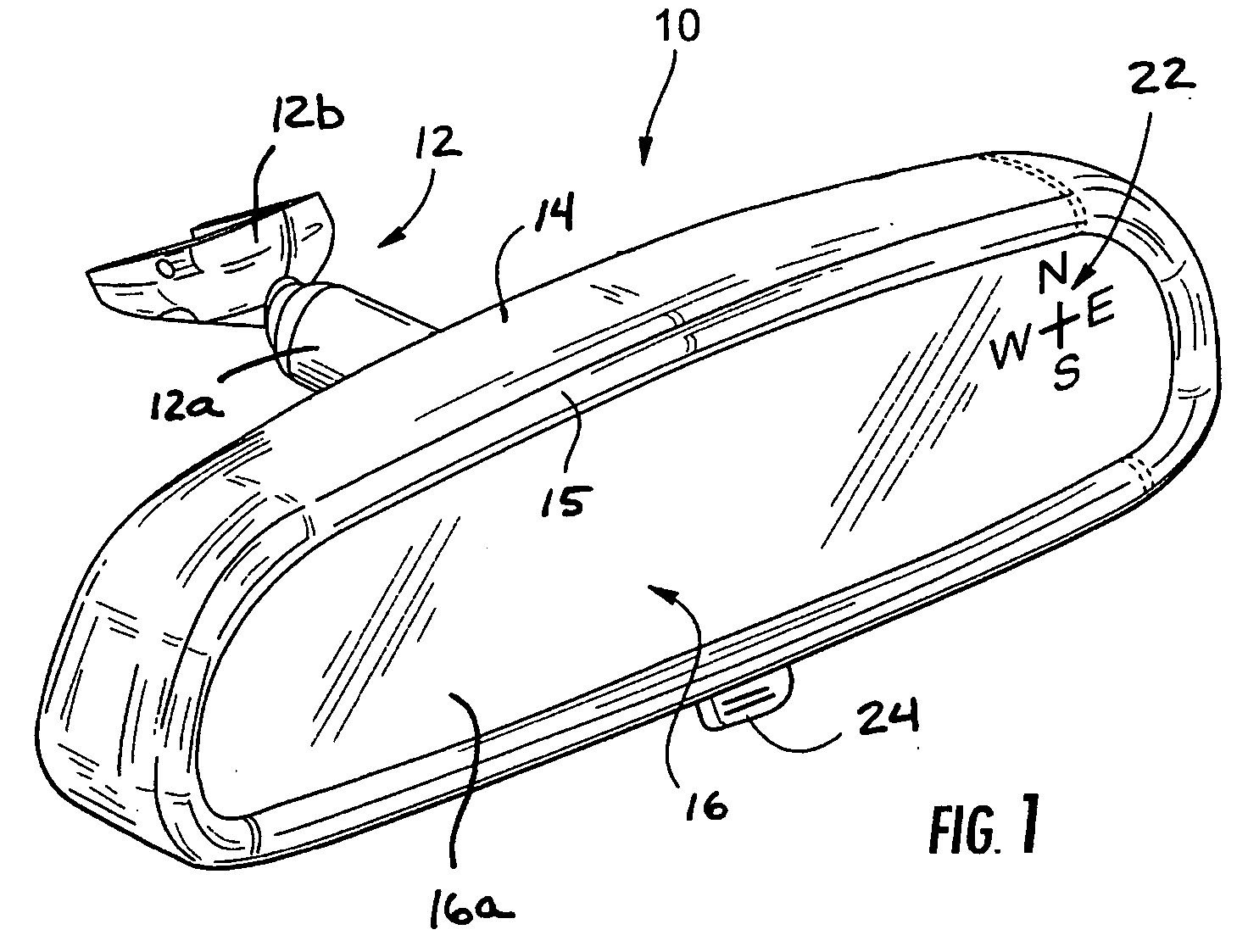
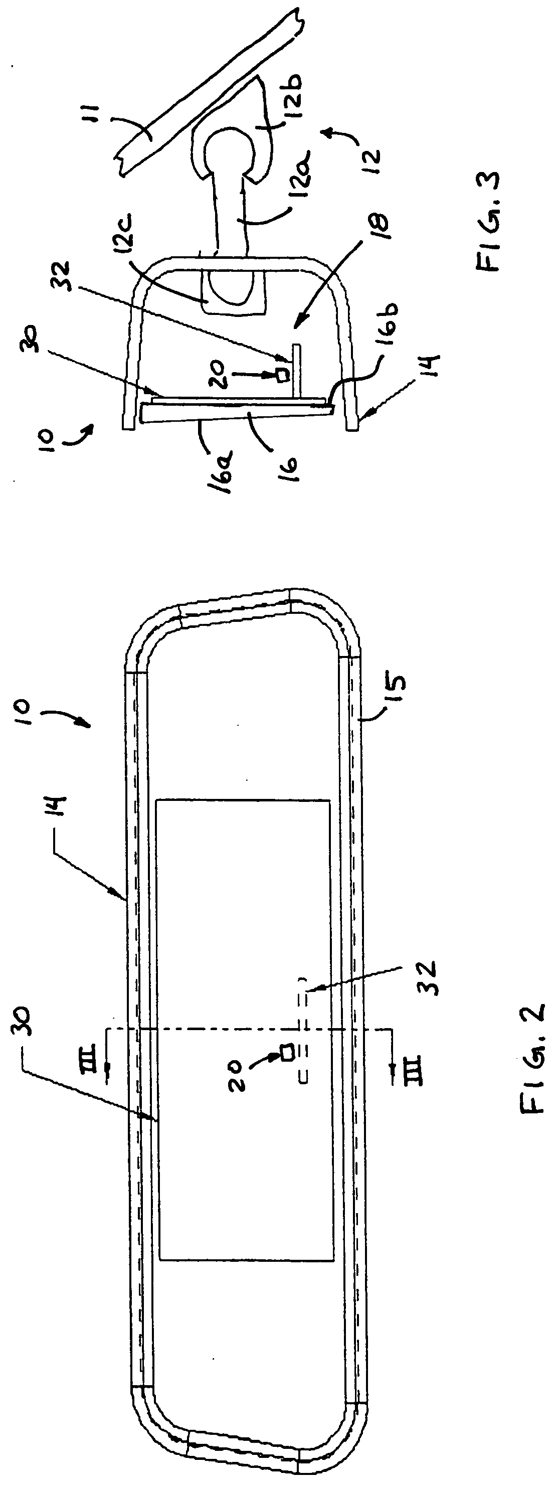
[0024] Referring now to the drawings and the illustrative embodiments depicted therein, a compassized prismatic interior rearview mirror assembly or system 10 includes a double pivot or double ball mounting arrangement 12 for pivotally or adjustably mounting a casing 14, bezel portion 15 and prismatic reflective element 16 of mirror assembly 10 relative to an interior portion of a vehicle, such as to an interior surface of a windshield 11 of a vehicle or the like (FIGS. 1-3). The mirror assembly 10 includes a compass system 18, which includes a magnetoresponsive compass sensor 20 and a display 22 for providing a display or indication of the directional heading of the vehicle, such as at the reflective element 16 of the mirror.

[0025] The mirror casing or housing 14 may comprise a polypropylene material or the like and is adjustably mounted to a mirror mount (not shown) positioned at an interior portion of a vehicle, such as a mirror mounting button on a windshield of the vehicle or ...


PUM


Abstract

An interior rearview mirror system for a vehicle includes an interior rearview mirror assembly, a casing having a reflective element, a compass sensor and a control. The compass sensor is disposed within the mirror casing and has a first magnetoresponsive sensing element and a second magnetoresponsive sensing element. The control receives a first signal indicative of a magnetic field sensed by the first magnetoresponsive sensing element and a second signal indicative of a magnetic field sensed by the second magnetoresponsive sensing element. The control determines that the casing is adjusted by an occupant of the vehicle in response to a change in the first and second signals being indicative of an abrupt movement of the casing about the mounting structure by an occupant of the vehicle. The control is operable to enter a rapid compensating mode to compensate for the mirror adjustment.

Description

CROSS REFERENCE TO RELATED APPLICATION [0001] The present claims benefit of U.S. provisional application, Ser. No. 60 / 636,931, filed Dec. 17, 2004 (Attorney Docket DON01 P-1196), which is hereby incorporated herein by reference in its entirety. FIELD OF THE INVENTION [0002] The present invention relates generally to interior rearview mirror assemblies for vehicles and, more particularly, to an interior rearview mirror assembly which includes a compass system. BACKGROUND OF THE INVENTION [0003] Interior rearview mirror assemblies which include a directional or compass display are known, such as the types disclosed in U.S. Pat. No. 5,802,727, which is hereby incorporated herein by reference. Typically, such mirror assemblies include a compass sensor, such as a magnetoresistive sensor, a magnetocapacitive sensor, a magnetoinductive sensor, a Hall effect sensor, or a flux gate sensor or the like, which is fixedly attached to the mirror mount that attaches the mirror assembly to a mirror...

Claims


Application Information

Patent Timeline
22 Jun 2006
Publication
US20060132939A1
IPC
G02B5/08
CPC
B60R1/12; B60R2001/1215; G01C17/38; G01C17/28
Inventors
BLANK, RODNEY K.; SCHIERBEEK, KENNETH L.