Electronic apparatus

a technology of electronic equipment and electronic components, applied in the direction of electrical equipment casings/cabinets/drawers, instruments, cooling/ventilation/heating modifications, etc., can solve the problems of increasing the noise of fans, reducing the efficiency of heat dissipation treatment, and requiring large-sized electronic equipment. , to achieve the effect of efficient heat dissipation treatmen

Inactive Publication Date: 2006-06-22
FUJITSU LTD
View PDF7 Cites 11 Cited by
  • Summary
  • Abstract
  • Description
  • Claims
  • Application Information

AI Technical Summary

Benefits of technology

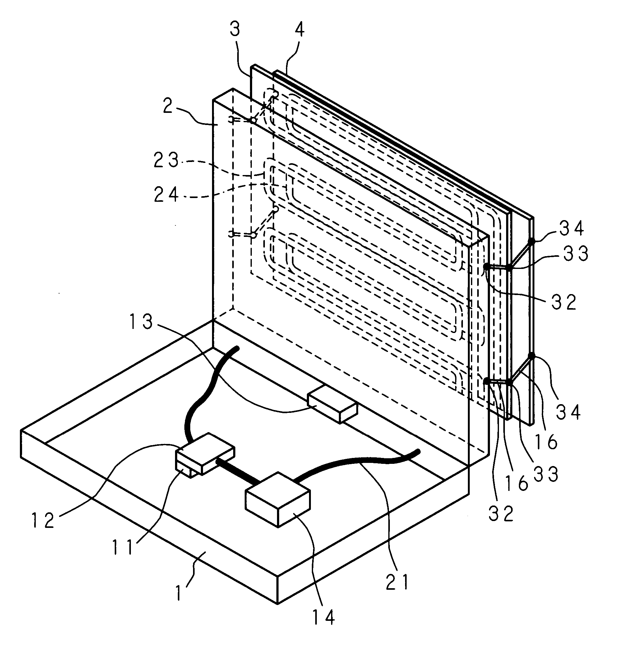
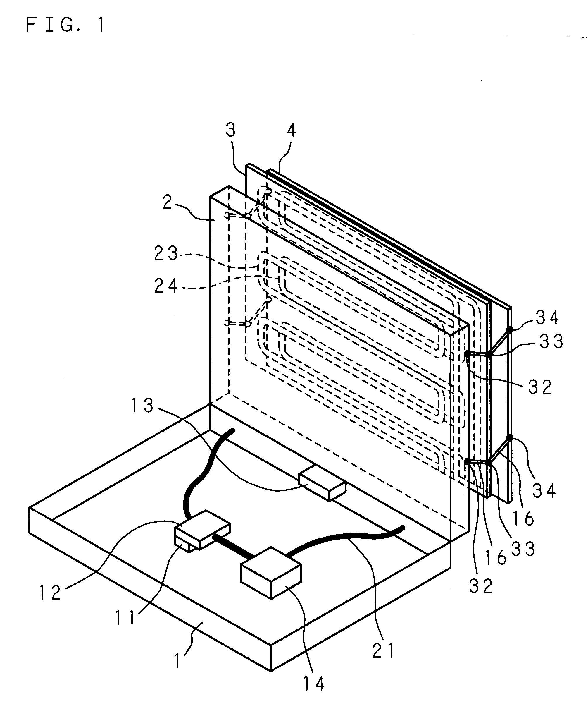
[0010] The present invention has been made in view of the situation described above, and it is an object of the present invention to provide an electronic apparatus which can efficiently perform heat dissipation treatment even when having a compact configuration, by freely movably providing a plurality of heat dissipation portions having flow paths for circulating a cooling liquid.
[0011] Another object of the present invention is to provide an electronic apparatus that can efficiently perform the heat dissipation treatment even when having a compact configuration, by controlling a flow rate of the cooling liquid flowing through the flow path which each of the plurality of heat dissipation portions has.
[0012] There is provided an electronic apparatus according to the present invention including a main body portion that generates heat and a cover body portion that covers the main body portion, and discharging the heat generated in the main body portion to the outside with a cooling liquid, wherein a plurality of heat dissipation portions having flow paths of the cooling liquid are provided in the cover body portion, and a distance between the cover body portion and the heat dissipation portion, and a distance between the adjacent heat dissipation portions are variable. According to the electronic apparatus configured as above, the plurality of heat dissipation portions having flow paths of the cooling liquid are provided at the backside of the cover body portion, so that a heat dissipation area is increased to thereby increase heat dissipation efficiency. Moreover, by making these heat dissipation portions to be movable, the distance between the cover body portion and the heat dissipation portion, and the distance between the adjacent heat dissipation portions are variable, so that air is made to flow between the cover body portion and the heat dissipation portion, and between adjacent heat dissipation portions, thereby making it possible to obtain a large heat dissipation effect. Since the plurality of heat dissipation portions having the flow paths of the cooling liquid are freely movably provided in the cover body portion, it is possible to efficiently perform the heat dissipation treatment even when having a compact configuration.
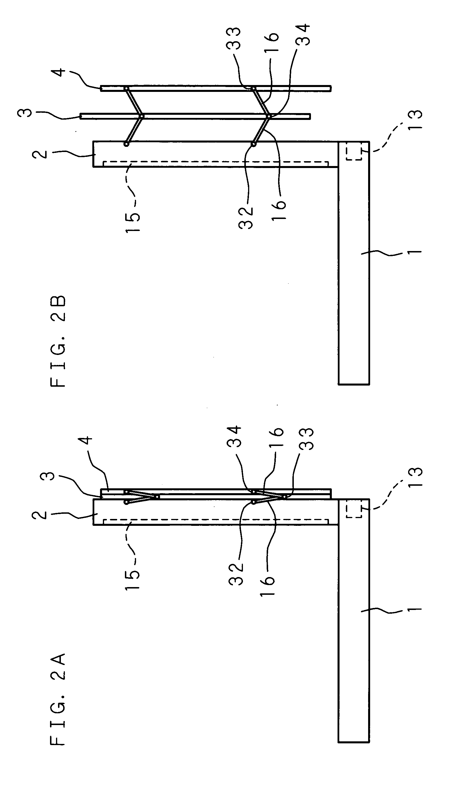
[0013] The electronic apparatus according to the present invention can change a distance between the cover body portion and the heat dissipation portion, and a distance between the adjacent heat dissipation portions. According to the electronic apparatus configured as above, when the cover body portion is opened, the distance between the cover body portion and the heat dissipation portion and the distance between adjacent heat dissipation portions are increased to thereby obtain the large heat dissipation effect, and when the cover body portion is closed, those distances are reduced to thereby house the plurality of heat dissipation portions therein compactly. Since according to an open / close operation of the cover body portion, the large heat dissipation effect is obtained when opened, and the heat dissipation portions are housed compactly when closed, it is possible to efficiently perform the heat dissipation treatment even when having a compact configuration.
[0015] There is provided an electronic apparatus according to the present invention having a main body portion that generates heat and discharging the heat generated in the main body portion to the outside with a cooling liquid, comprising a plurality of heat dissipation portions that have flow paths of the cooling liquid in a mode of communicating with each other in parallel or in series, and a controlling unit that controls a flow rate of the cooling liquid flowing through the flow path which each of the plurality of heat dissipation portions has. According to the electronic apparatus configured as above, the flow rate of the cooling liquid flowing through the flow path of each of the plurality of heat dissipation portions that are communicated in parallel or in series is controlled by the controlling unit. Therefore, that makes it possible to provide a large heat dissipation area and a high cooling capacity, and exhibit an efficient heat dissipation characteristic.

Problems solved by technology

However, when using a large-sized heat sink, there may arise a problem that a large-sized electronic apparatus is also required in order for the heat sink to be incorporated therein.
Meanwhile, in order to achieve a performance improvement of the cooling fan, large-sizing of a fan structure, an increase in a rotational frequency of the cooling fan, or the like is required, but there may arise a problem that this technique cannot prevent the electronic apparatus from being large-sized or a fan noise from being increased.
Particularly, in a notebook type computer, in addition to the cooling capability, portability, that is, the size and weight of the apparatus will become an important factor, and silence, that is to say, the apparatus works quietly during operation will also be an essential factor, but the countermeasures for improving the cooling capability described above are contradictory to those.

Method used


Image

  • Electronic apparatus
  • Electronic apparatus
  • Electronic apparatus

Examples


first embodiment

[0043]FIG. 4 is a perspective view showing a configuration of an electronic apparatus according to a first embodiment; FIGS. 5A through 5D are side views showing an open / close operation of two heat-dissipating boards, and FIG. 6 is a side view of the electronic apparatus including a structure of an expanded outer heat-dissipating board. In FIGS. 4 through 6, the same number is given to a portion the same as or similar to that of FIGS. 1 through 3. Incidentally, in FIG. 4, illustration of the flow path of the cooling liquid formed in the inner heat-dissipating board 3 and the outer heat-dissipating board 4 is omitted.

[0044] According to the first embodiment, the beam 16 is arranged between a pole brace 31 provided at the side of the first housing 1 and a pivot 34a in the center of the outer heat-dissipating board 4. The pivot 34a of outer heat-dissipating board 4 is provided on a slider 35 that slides on the side of the outer heat-dissipating board 4 (refer to FIG. 6), a position of...

second embodiment

[0048]FIG. 7 is a perspective view showing a configuration of an electronic apparatus according to a second embodiment, and FIGS. 8A through 8D are side views showing an open / close operation of two heat-dissipating boards. In FIGS. 7 and 8, the same number is given to a portion the same as or similar to that of FIGS. 1 through 6. Incidentally, in FIG. 7, illustration of the flow path of the cooling liquid formed in the inner heat-dissipating board 3 and the outer heat-dissipating board 4 is omitted.

[0049] According to the second embodiment, a beam 16a is arranged between a pole brace 31a provided on the side of the first housing 1 and the pivot 34 in the center of the outer heat-dissipating board 4. A motor 17 is coupled to the pole brace 31a, the pole brace 31a is driven by the motor 17 which is driven and controlled by a motor control unit 18, and an angle of gradient of the beam 16a can be arbitrarily adjusted.

[0050] Moreover, an angle sensor 19 that detects an opening / closing ...

third embodiment

[0054]FIG. 9 is a perspective view showing a configuration of an electronic apparatus according to a third embodiment, and FIGS. 10A and 10B are side views showing an open / close operation (FIG. 10A shows an open state, and FIG. 10B shows a close state) of two heat-dissipating boards. In FIGS. 9 and 10, the same number is given to a portion the same as or similar to that of FIGS. 1 through 8. Incidentally, in FIG. 9, illustration of the flow path of the cooling liquid formed in the inner heat-dissipating board 3 and the outer heat-dissipating board 4 is omitted.

[0055] According to the third embodiment, a beam 16b and a beam 16c are arranged between the pole brace 31a provided on the side of the first housing 1 and a lower pivot 33a of the inner heat-dissipating board 3, and a lower pivot 34b of the outer heat-dissipating board 4, respectively. The pivot 33a is provided on the slider 35 that slides on the side of the inner heat-dissipating board 3, and the pivot 33a moves on the side...


PUM


Abstract

A body flow path in a first housing having an MPU element communicates with an inner flow path and outer flow path formed in an inner heat-dissipating board and an outer heat-dissipating board, respectively, and a pump drives a cooling liquid to circulate in these flow paths. A beam is arranged between a pivot provided in a second housing and a pivot provided in the inner heat-dissipating board, a beam is arranged between the pivot of the inner heat-dissipating board and a pivot provided in the outer heat-dissipating board, and the inner heat-dissipating board and the outer heat-dissipating board are movable to the second housing. According to the operation of opening the second housing, a distance between the second housing and the inner heat-dissipating board, and a distance between the inner flow path and the outer flow path are increased.

Description

CROSS-REFERENCE TO RELATED APPLICATIONS [0001] This Nonprovisional application claims priority under 35 U.S.C.§119(a) on Patent Application No. 2004-366484 filed in Japan on Dec. 17, 2004, the entire contents of which are hereby incorporated by reference. BACKGROUND OF THE INVENTION [0002] The present invention relates to an electronic apparatus that performs heat dissipation treatment using a circulating cooling liquid. [0003] An electronic apparatus, such as a desktop type computer, a notebook type computer, and a mobile communication device, is provided with a microprocessor (MPU). In recent years, with an improvement in processing speed of the microprocessor, and enhancement features and advanced performances of the microprocessor, there is an increasing tendency in heating value during operation. In order for the microprocessor to maintain stable operation, generated heat must be quickly discharged to the outside to thereby increase heat dissipation efficiency. [0004] For that ...

Claims


Application Information

Patent Timeline
Patent Type & Authority Applications(United States)
IPC IPC(8): G06F1/20
CPCG06F1/203G06F2200/201H05K7/20
Inventor UCHIDA, HIROKITANIGUCHI, JUNTOKUHIRA, HIDESHIISHINABE, MINORUISHIDUKA, MASANOBUDATE, HIROAKI
Owner FUJITSU LTD
Why Eureka
Try Eureka