Supercharge Your Innovation With Domain-Expert AI Agents!

Tilt detection apparatus, hologram apparatus, tilt correction method for medium, and tilt correction method for hologram medium

a technology of tilt detection and hologram, which is applied in the direction of digital signal error detection/correction, instruments, recording signal processing, etc., can solve the problems of not accurately incidenting the reference beam and disabling the reproduction of digital data, and the inability to record digital data as a hologram at the desired position in the hologram medium,

Inactive Publication Date: 2006-06-22
SANYO ELECTRIC CO LTD
View PDF3 Cites 10 Cited by
  • Summary
  • Abstract
  • Description
  • Claims
  • Application Information

AI Technical Summary

Benefits of technology

[0016] Hence, an object of the present invention is to provide a tilt detection apparatus, a hologram apparatus, a tilt correction method for a medium, and a tilt correction method for a hologram medium, which can correct the tilt of a hologram medium tilted with respect to a reference position.
[0023] According to the present invention, there are provided a tilt detection apparatus, a hologram apparatus, a tilt correction method for a medium, and a tilt correction method for a hologram medium, which can correct the tilt of a hologram medium tilted with respect to a reference position.

Problems solved by technology

The tilt of the hologram medium may cause the angle difference between the incidence angle θ and the reproducing angle θ to be greater than the angle difference Δθ thereby making the reproducing reference beam not be accurately incident and disabling the reproduction of digital data.
Also, when recording digital data onto the hologram medium, the digital data may not be recorded as a hologram at a desired position in the hologram medium.
In particular, where the hologram medium is shaped like a disk, since being thin, it is difficult to hold the hologram medium horizontal with respect to the reference position, and the hologram medium may be tilted.
As a result, due to distortion that occurs in mounting hologram media on the hologram apparatus or centrifugal force exerted on the hologram media when rotating, the hologram media may be tilted with respect to the reference position.

Method used


Image

  • Tilt detection apparatus, hologram apparatus, tilt correction method for medium, and tilt correction method for hologram medium
  • Tilt detection apparatus, hologram apparatus, tilt correction method for medium, and tilt correction method for hologram medium
  • Tilt detection apparatus, hologram apparatus, tilt correction method for medium, and tilt correction method for hologram medium

Examples


Embodiment Construction

[0037] At least the following matters will be made clear by the explanation in the present specification and the description of the accompanying drawings.

>

===Overall Configuration of Tilt Detection Apparatus / Hologram Apparatus===

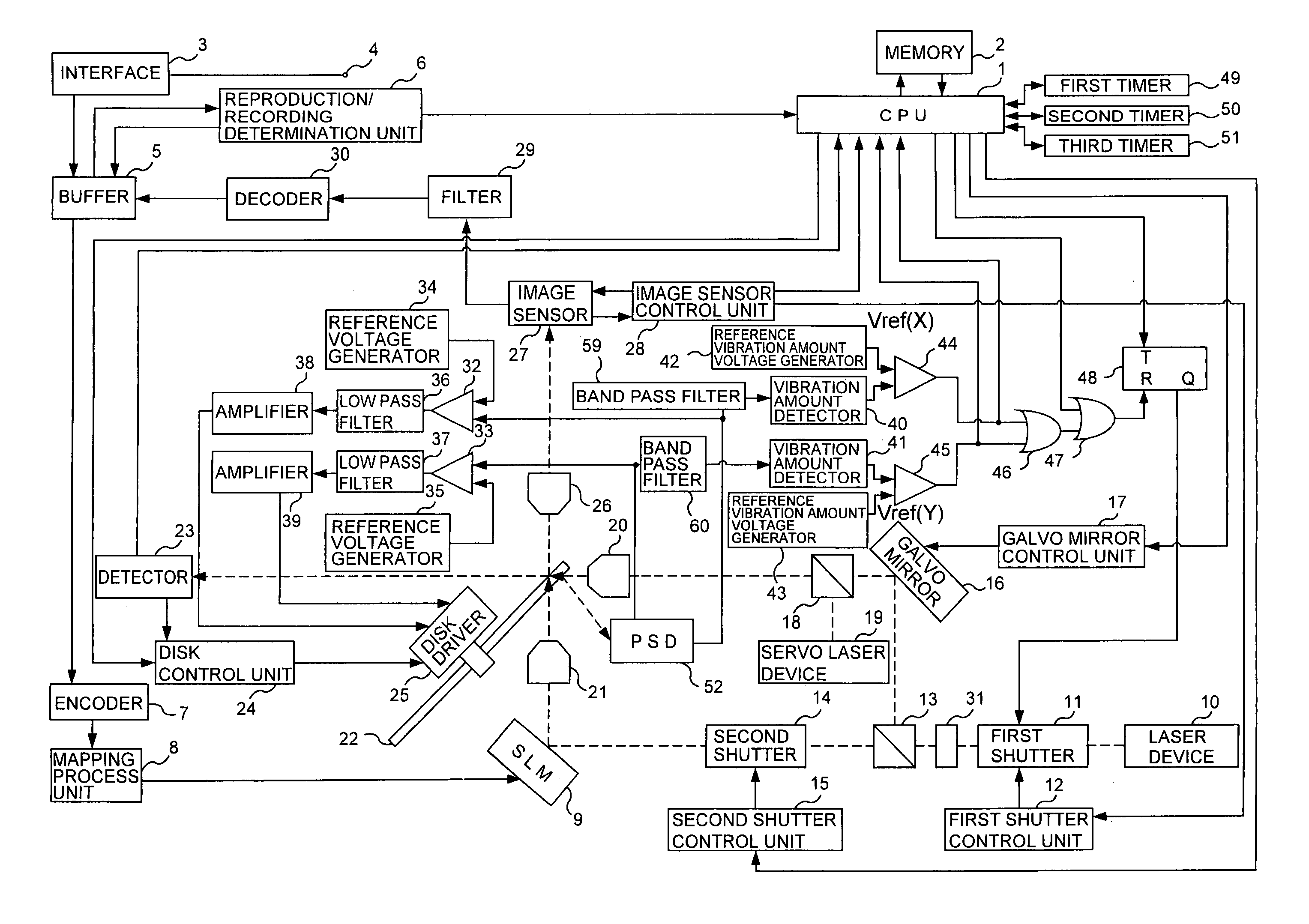
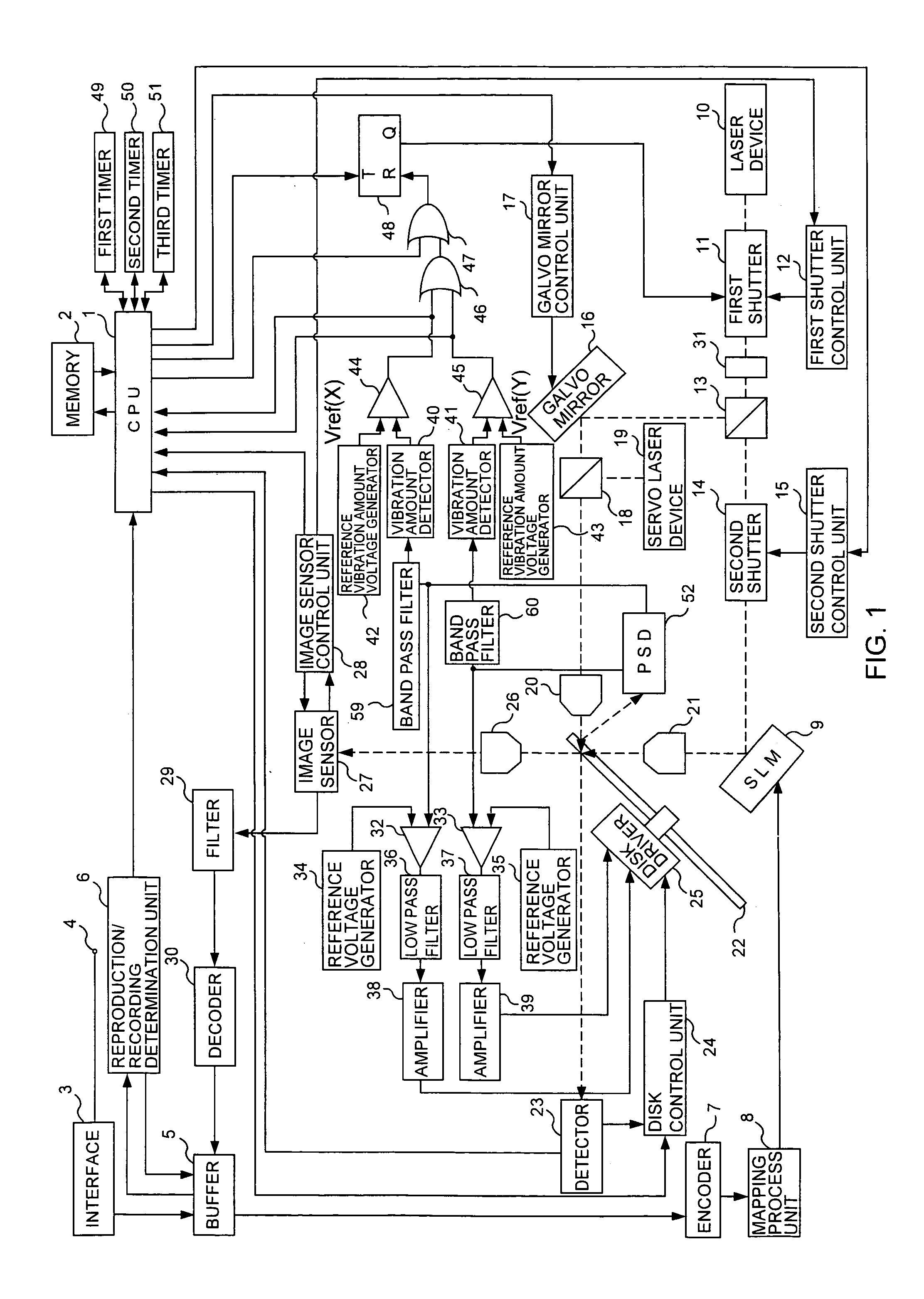
[0038] A tilt detection apparatus / hologram apparatus according to the present invention will be described with reference to FIGS. 1, 6, 9, 10. FIG. 1 is a functional block diagram illustrating an example of the overall configuration of the tilt detection apparatus / hologram apparatus according to the present invention. FIG. 6 is a diagram illustrating the reflection and transmission of a servo laser beam (tilt detection beam) when a disk medium 22 (a hologram medium) is tilted with respect to a reference position A. In FIG. 6, a disk medium 22 indicated by the broken line is a disk medium 22 in the reference position A, and a disk medium 22 indicated by the solid line is a disk medium 22 tilted with respect to the reference position A. FIG. 9 is a detailed ...


PUM


Abstract

A tilt detection apparatus for a medium comprises a tilt detection beam generator that makes a tilt detection beam incident ion a medium to detect whether the medium is tilted with respect to a reference position; a light reception unit that receives the tilt detection beam that after striking the medium, has come from the medium; and a correction output unit that outputs a signal to correct a tilt of the medium, based on a difference in light reception position on the light reception unit between a position at which the light reception unit receives the tilt detection beam and a position at which the light reception unit is to receive the tilt detection beam when the medium is in the reference position.

Description

CROSS-REFERENCE TO RELATED APPLICATIONS [0001] The present application claims priority from Japanese Patent Application No. 2004-370018 filed on Dec. 21, 2004, which is herein incorporated by reference. BACKGROUND OF THE INVENTION [0002] 1. Field of the Invention [0003] The present invention relates to a tilt detection apparatus, a hologram apparatus, a tilt correction method for a medium, and a tilt correction method for a hologram medium. [0004] 2. Description of the Related Art [0005] Among hologram media adapted to record digital data as holograms is a photosensitive resin (e.g., photopolymer) sealed between glass substrates. [0006] To record digital data on a hologram medium as a hologram, a laser beam from a laser device is first split into two beams by a PBS (Polarization Beam Splitter). Then, one of the two beams (hereinafter referred to as reference beam) and a laser beam (hereinafter referred to as data beam) produced by the other beam irradiating an SLM (Spatial Light Mod...

Claims


Application Information

Patent Timeline
IPC IPC(8): G11B7/00
CPCG11B7/0065G11B7/0956
Inventor KOGURE, KAZUYA
Owner SANYO ELECTRIC CO LTD
Features
  • R&D
  • Intellectual Property
  • Life Sciences
  • Materials
  • Tech Scout
  • Unparalleled Data Quality
  • Higher Quality Content
  • 60% Fewer Hallucinations
Learn More